Balloon Framing

Between Timber Framing and modern Platform Framing was an intermediate style of framing a building called ‘Balloon Framing’.
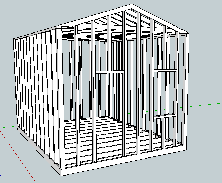
Balloon Frame 3D Model
Figure 1: Balloon Frame 3D Model

This method of framing was radical for its time. Started around the 1830s and steadily gaining in popularity through the end of the 19th century Balloon framing ushered in a new generation of building supplies and builders who benefited from and drove the advent of ever cheaper machine made nails, consistent milled lumber, and more efficient transportation methods (Rail box-cars etc). Beyond the technological advancements in the materials production and transportation this building method caught on quickly as buildings framed in this manner could be built cheaply with non-skilled labor and common nails and tools, thus farmers and do-it-yourselfers could build what they needed with a far shallower learning curve when compared to all the advanced joinery traditional timber framing required. This was invaluable to frontier areas where traditional carpenters and joiners were in short supply.
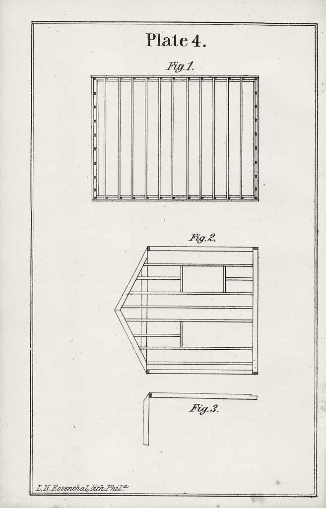
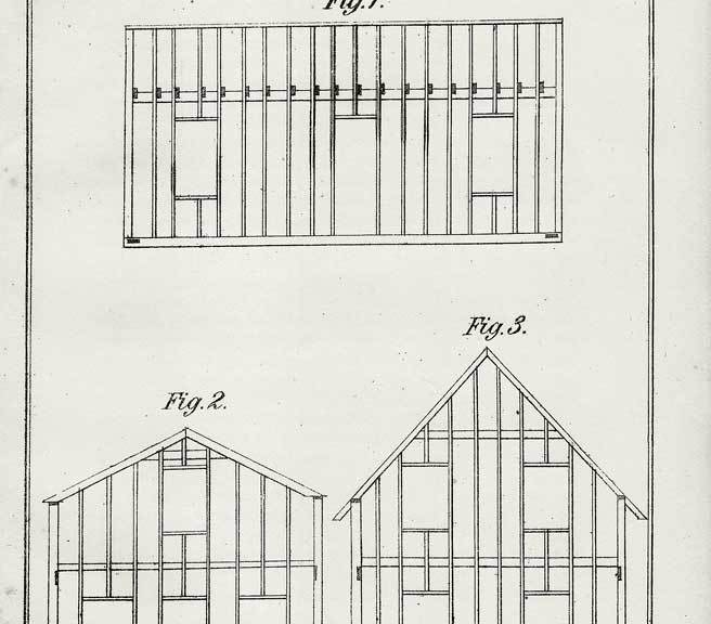
Bell's Carpentry Made Easy Plate 4
Figure 2: Bell’s Carpentry Made Easy Plate 4

In the mid-west and plains states in particular you see a lot of balloon framed houses during this period as they had good access to the mills producing these building materials, a desire to quickly build and expand existing buildings and in some areas a dearth of heavy timber needed to build in the older styles. Even in more populated areas back east you’ll see many of the Shingle Style and Victorian homes and Triple-Deckers were framed this way, though certainly some more austere farm houses of this period were also framed in this manner as it was an economical way to build. If you look carefully at some of the design details you can see how tastes and designs changed to make use of the dominant building supplies of the time. You’ll see higher ceiling heights, various bump outs, towers etc that were more easily executed with this style of framing and in keeping with the prevailing styles of the day. (See Figure 3)
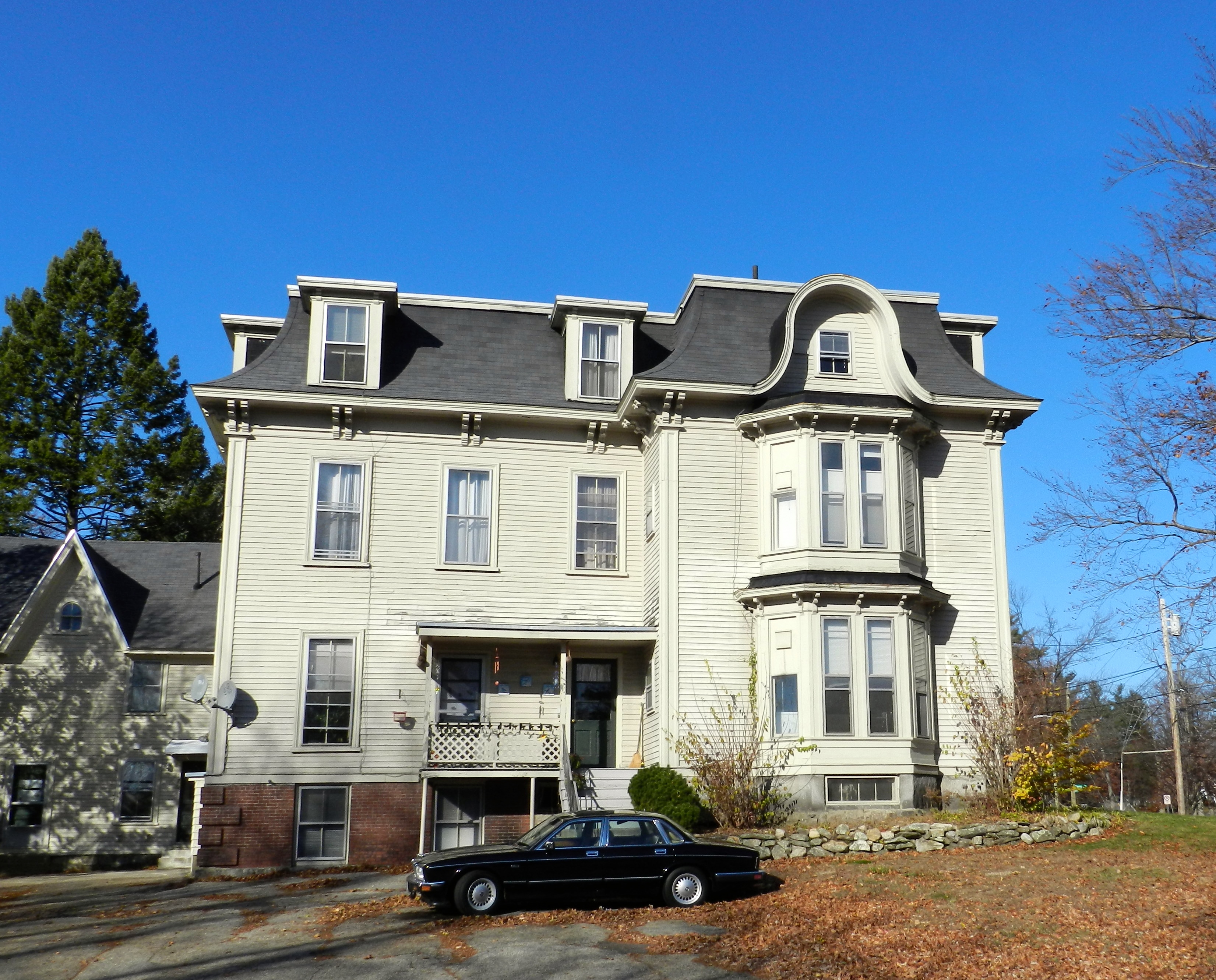
Mansard Victorian in Manchester NH
Figure 3: Mansard Victorian in Manchester NH

Balloon framing made use of common sized lumber coming from mills — the first real large scale use of 2x4s, 2x8s, 1x10s etc in framing a building and marked a transition from the heavy timbered buildings of the east coast of America and the ‘Old World’ that preceded it. In the earlier part of this period a 2×4 was actually 2″x4″ in some areas as opposed to the ‘nominal’ sizes we have today wherein a 2×4 is 1.5″x3.5″ by the time it makes it to a modern lumberyard, but that is a post for another day. The weight of the building was dispersed across a series of smaller consistent studs as opposed to a few heavy posts. Also notable was the fact that the studs ran from sill to plate, thus requiring the 2nd and 3rd floors to be ‘hung’ from the studs via ledger or ‘ribbon’ boards. (See Figures 2 and 4)
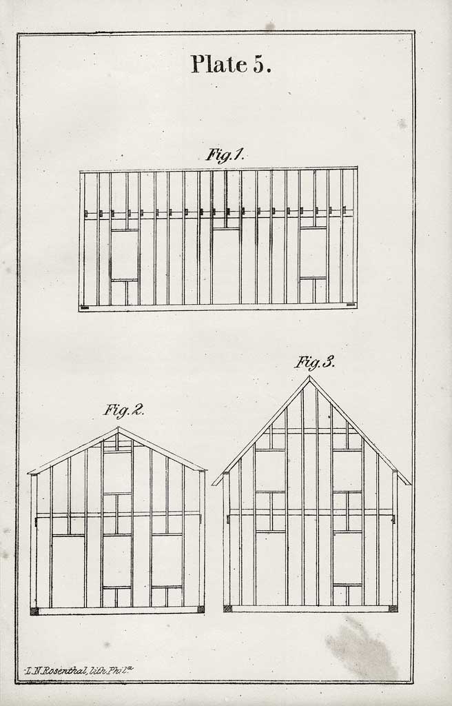
Bell's Carpentry Made Easy Plate 5
Figure 4: Bell’s Carpentry Made Easy Plate 5

A great period resource for information about Balloon Framing is William Bell’s “Carpentry Made Easy: The Science and Art of Framing”. While Bell was not the first author to extol the virtues of Balloon Framing he may have been one of the most prolific. His ‘Carpentry Made Easy’ book was published continuously from 1858-1904. 46 years is quiet a testament to the information he provided. The book’s longevity is largely due to how the information is provided. Bell starts with a detailed section on basic math and geometry for carpenters and the moves into framing. He covers Balloon Framing for homes and modest sized buildings and moves on to heavy timber framing for industrial buildings, bridges, spires and the like. Bell was a trained carpenter and joiner and speaks the reader in a clear and concise way that was agreeable to most carpenters. Bell goes into technical detail but did so in such a way that any reasonably skilled carpenter could take this information and apply it to the project at hand. His words still resonate well today — in fact using his descriptions I was able to build a detailed 3D model in Sketch-Up based on his instructions for how to build a Balloon Framed structure. (See Figures 1 and 5). I’m sure that many a house carpenter had a dog-eared copy of this book in their toolbox and regularly referred to it over the years.

How fast did this transition happen?

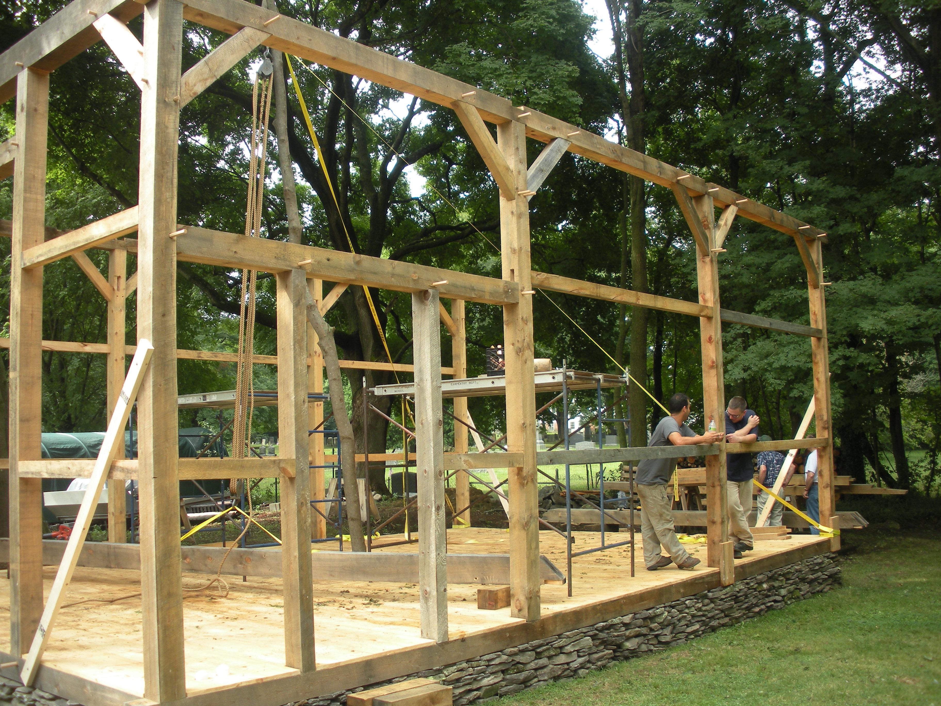
Like most major shifts in an industry the transition from Heavy Timber Framing to Balloon Framing did not happen over night. The word had to get out, it had to be evaluated, the supplies had to be ready and a host of macro-economic pressures had to come together in order to facilitate this change — a strong need to build economical housing for an exploding population etc. Like most things, some isolated or rural areas clung to the old ways for longer periods and some areas were more willing to try out these new techniques. Even cutting over in terms of technique was an evolutionary change. If you look closely at Figure 4 above you’ll see that the house shown there has Balloon Framed walls with a heavy timbered sill, which the author notes as the preferred way to go if heavy timber is available, as opposed to Figure 2 which shows a more traditional balloon framed sill made from 2x framing elements.

In broad terms this building method started in the 1830s, crescendo-ed during the 1880s-1930s giving way to modern Platform Framing which was an evolutionary advancement that built upon the strengths and lessons of this movement. Balloon Framing and it’s relative efficiencies greatly improved the living conditions of many Americans and others of modest means and the burgeoning middle class.
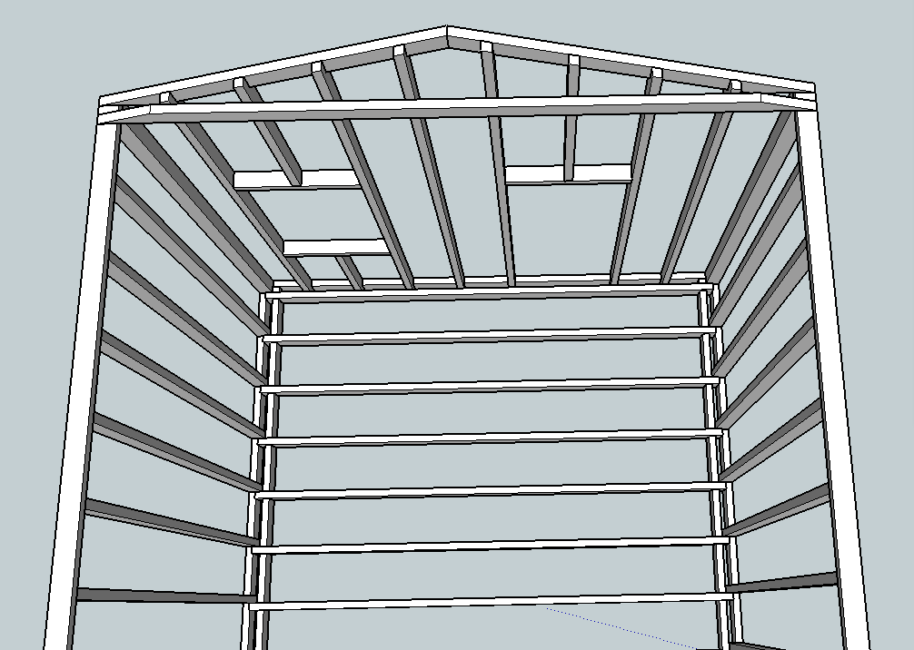
Balloon Frame Cutaway 3D Model
Figure 5: Balloon Frame Cutaway 3D Model To Show Joinery

Why did Balloon Framing disappear? Disadvantages and Demise

With Balloon Framing, you framed an entire wall at once from sill to top plate, thus requiring longer framing members. Once the wall was standing you needed to have ladders and scaffolding in order to ‘hang’ the upper floors from the ledger plates and studs. This required more labor compared to modern platform framing where each level builds upon the lower level, thus requiring less labor, scaffolding and smaller framing members.

In some larger Balloon Framed buildings you’d see some sagging towards central walls due to differential shrinking of the framing members — joists resting on ledger boards will move a different amount when compared to joists nailed into the side of as stud. This kind of differential can add up in a larger building and took time to manifest itself. (See Wikipedia here for a more detailed explanation)

While the above items are negatives for this system of framing the final nail in it’s coffin was how it performs in a fire. The inter-stud wall cavities that run from sill to plate worked like a chimney flue and helped to rapidly spread fire throughout a Balloon Framed building. To counter this, fire blocking can be installed between each floor, but this was labor consuming to install and not quite as good as the fire resistance you’ll see in a Platform Framed building. Even today when filling out an application for homeowners insurance you’ll often see questions related to this kind of framing.

What replaced Balloon Framing?

Around the 1930s the death toll and property loss data was starting to add up and folks looked to rectify the situation. The solution was Platform Framing. In a nutshell you’d build a platform of sill, joists, rim joists and sub-flooring, use this as a platform to build the walls for one floor, you’d tilt up and nail off the walls, then build another platform on top of that until you top out your building. This method required less labor, shorter framing members and by breaking up the wall cavities at each floor provided better fire resistance.  After World War II the post war building boom accelerated the need for even more housing and faster build completion times. At this time we started to see the introduction of studs 16″ to accommodate sheet goods (Plywood and later OSB) in regular sizes as a replacement for more labor and material intensive traditional sheathing. And in a similar manner vinyl siting replaced genuine clapboards etc etc until you get to present day building materials and practices.

Conclusion

We don’t often see or hear much about Balloon Framing today as it has fallen out of favor in the building community, but it’s impact can be felt today in any Platform Framed structure that benefited from all the lessons learned by this earlier incarnation of efficient home building. I hope that the next time you are examining the framing of a Balloon Framed structure you’ll take a look and see what lessons it can teach you.

Take care,
-Bill

P.S. If you’d like to read William Bell’s “Carpentry Made Easy: The Science and Art of Framing” (1858) you can get a copy from the Toolemera Press here. It was a great read with interesting sections on timber framing, compound roof joinery, bridge-building, spire making and other interesting building topics above and beyond the Balloon Framing and carpenter’s geometry I mention in this article.

** Plates 4 and 5 of from Bell’s Book are provided via Gary Roberts of the Toolemera Press and used with his permission.
Treenails, Trunnels, Pins and Pegs

Treenails, Trunnels, Pins and Pegs — all terms used to describe the wooden nail-like fastener used in timber frame construction. I needed to make a large number of them for an upcoming project and thought you might also enjoy seeing what it takes to make these deceptively simple looking pins.

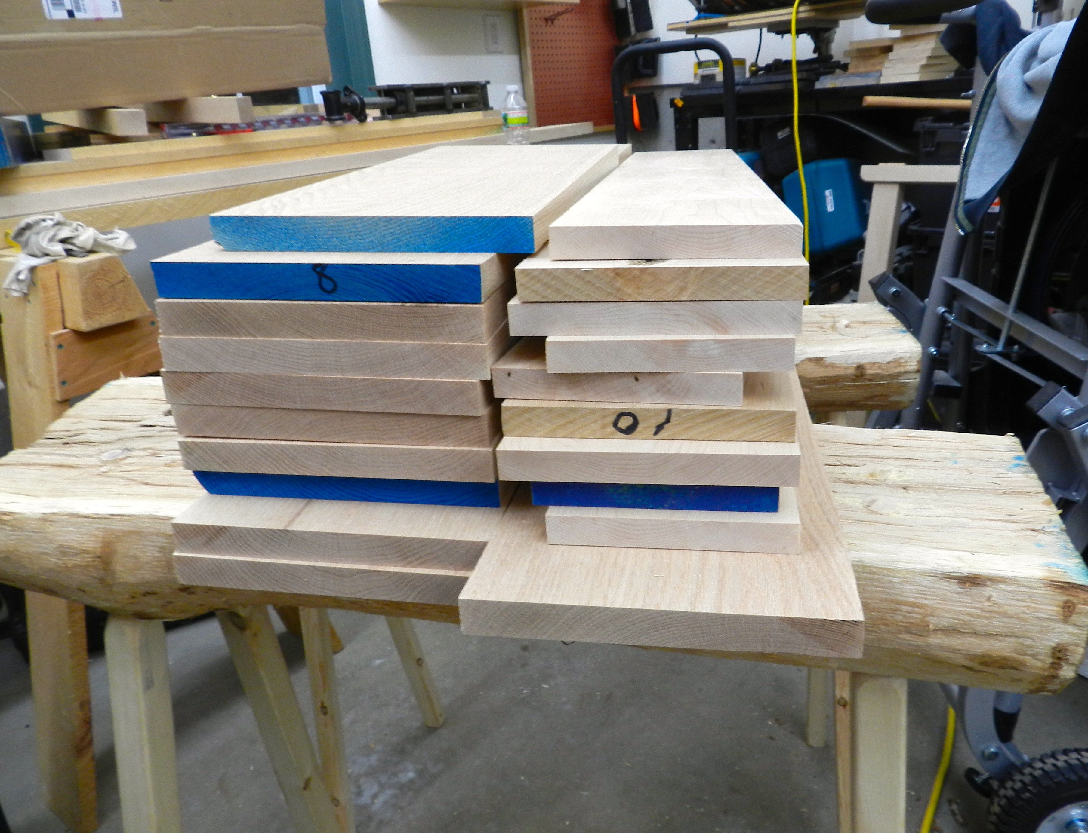
White Oak and Hard Maple stock ripped, thickness planed and jointed
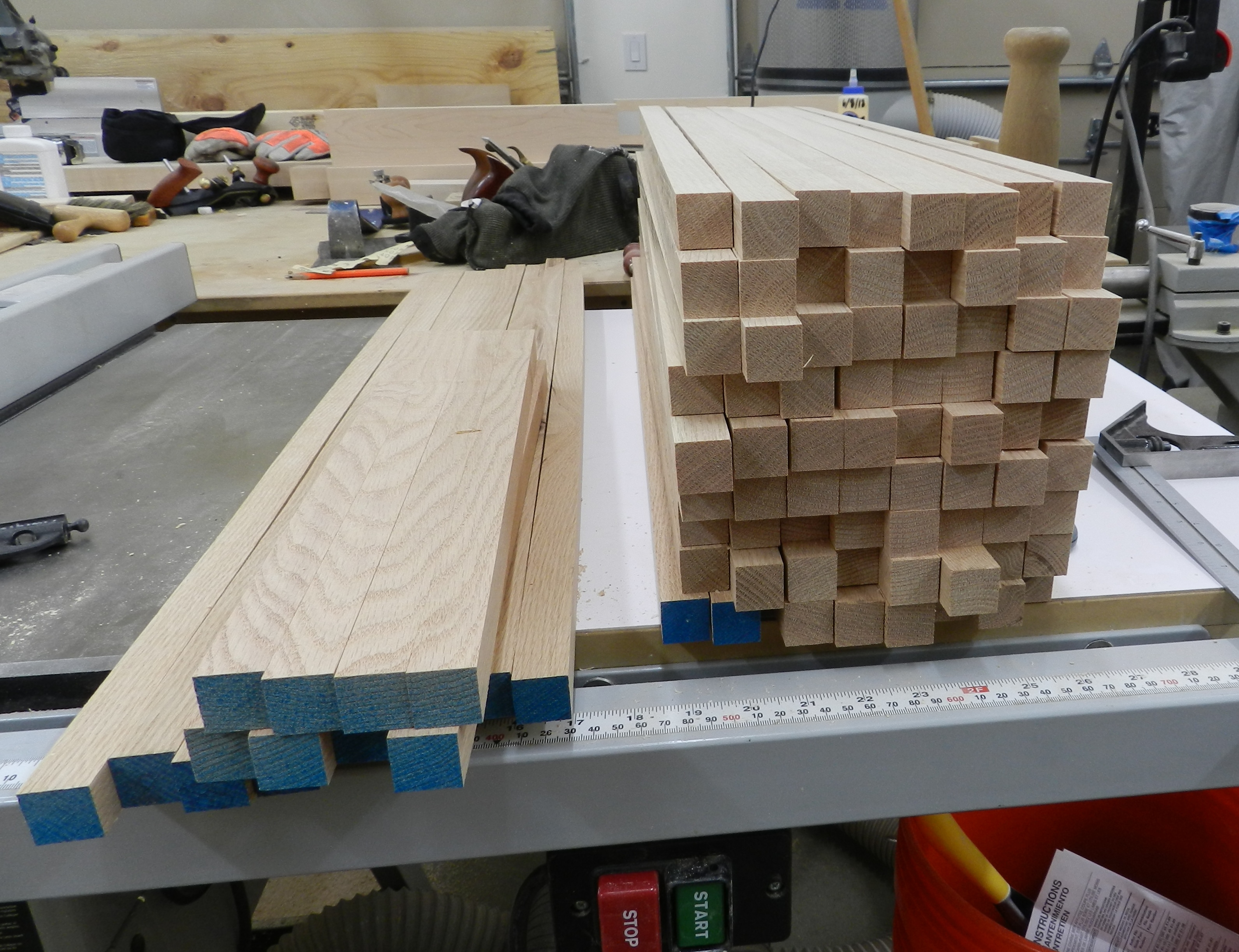
(1) White Oak and Hard Maple stock ripped, thickness planed and jointed

Where did all those names come from?

Like most things that predate modern recorded history I’ve read many conflicting theories on where these terms came from, so what I relay here is based on my own experiences in this field; your mileage may vary. Timber framing dates back thousands of years and can be found in early civilizations around the world in many different forms. What all these structures had in common was the joining of heavy timbers using traditional joinery and large mortise an tenon joints that were pinned together using large wood fasteners.

These fasteners are known by a lot of colloquial names, the most common of which I describe in this post. Most literally treenails (or trenails in some places) is the term for nails made from a tree. Trunnels is derived from the pronunciation of treenails and at times reserved for larger treenails used in very large buildings or ships, sometimes even wedged so they do not back out. Pegs tends to be a more modern term for treenails and pins tends to be used for smaller scale work though many timber framers I know today use it regularly. Having said all this I’ve heard all of these terms used inter-changeably at times by both novices and seasoned professionals, so feel free to use the term(s) that best suit your work and locale.

The bottom line is ‘a pin by any other name will hold your building together just as well.‘ (provided you heed my tips below 😉 )

Stock ripped down into square blanks
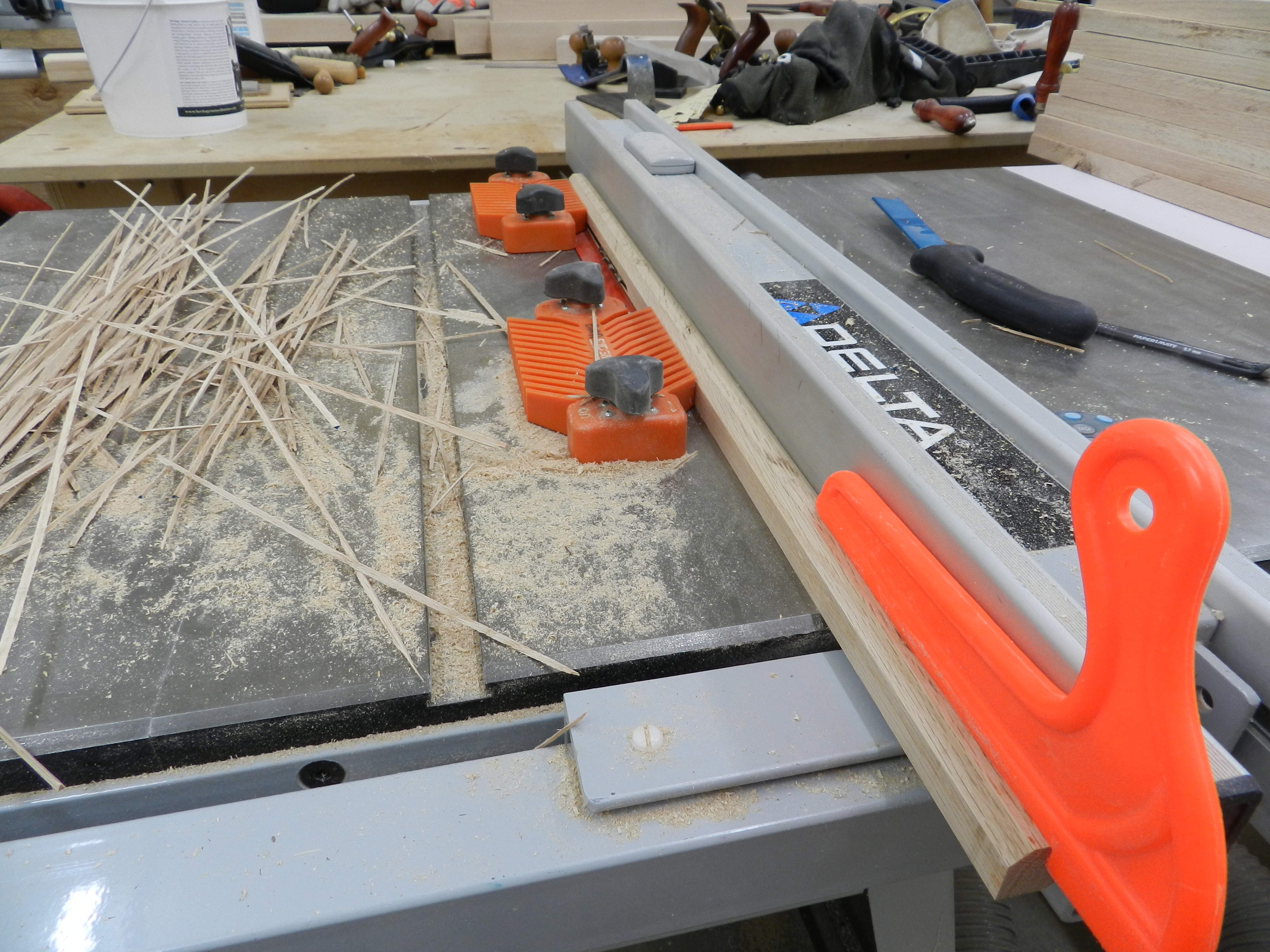
(2) Stock ripped down into square blanks

How do you go about making these pins?

Traditionally pins were split out of green wood, shaved down with a draw knife and shave horse and allowed to season. Then touched up again when dry. Since I have to make a few hundred of these, being a practical modern joiner I will make use of my table saw and some high quality kiln dried lumber. Most of the stresses in a timber frame are carried by the joints and not the pins, and white oak is very resistant to shearing forces so I am not worried about the wood not being split out for this usage. (I’m building a square rule, late 19th century style frame from milled eastern white pine, so by that point the pins likely were made the same way I go about it)

For the scale of timber framed buildings I generally work on — homes, barns and sheds, I’m usually using a 7/8″ ships auger bit to drill holes for pins. Most tenons I work with are generally 1.5″-2″ thick eastern white pine and based on experience and reference tables I’ve found this size to work well for me.

I learned to timber frame while at NBSS and with that my framing has a proclivity for historic precedents. The historic buildings I work on all had octagoned pegs which worked well for hundreds of years and can be made more easily when compared to the expensive turned pegs you see some modern supply houses offer for upwards of $2 each. For a draw bored joint, I feel the octagon pegs look better and hold better compared to the CNC turned pins. (More on that later)

Making octagons out of the square blanks
(3) Making octagons out of the square blanks

1.) I start off by milling down my rough 4/4 white oak stock to be 7/8″ thick, then I joint an edge on each board (See photo 1). I then crosscut each board to be about 30-3/8″ long. (Each of these boards should yield 3 sets of 10″ long pegs)

2.) Next I rip each of those boards into 7/8″ square sticks (See photo 2)

3.) Tilt the blade on your table to 45″ and turn each of those square blanks into an octagon. The use of feather-boards will help you be consistent. (See photo 3)

Chopping several blanks at a time on the chop saw using a stop block
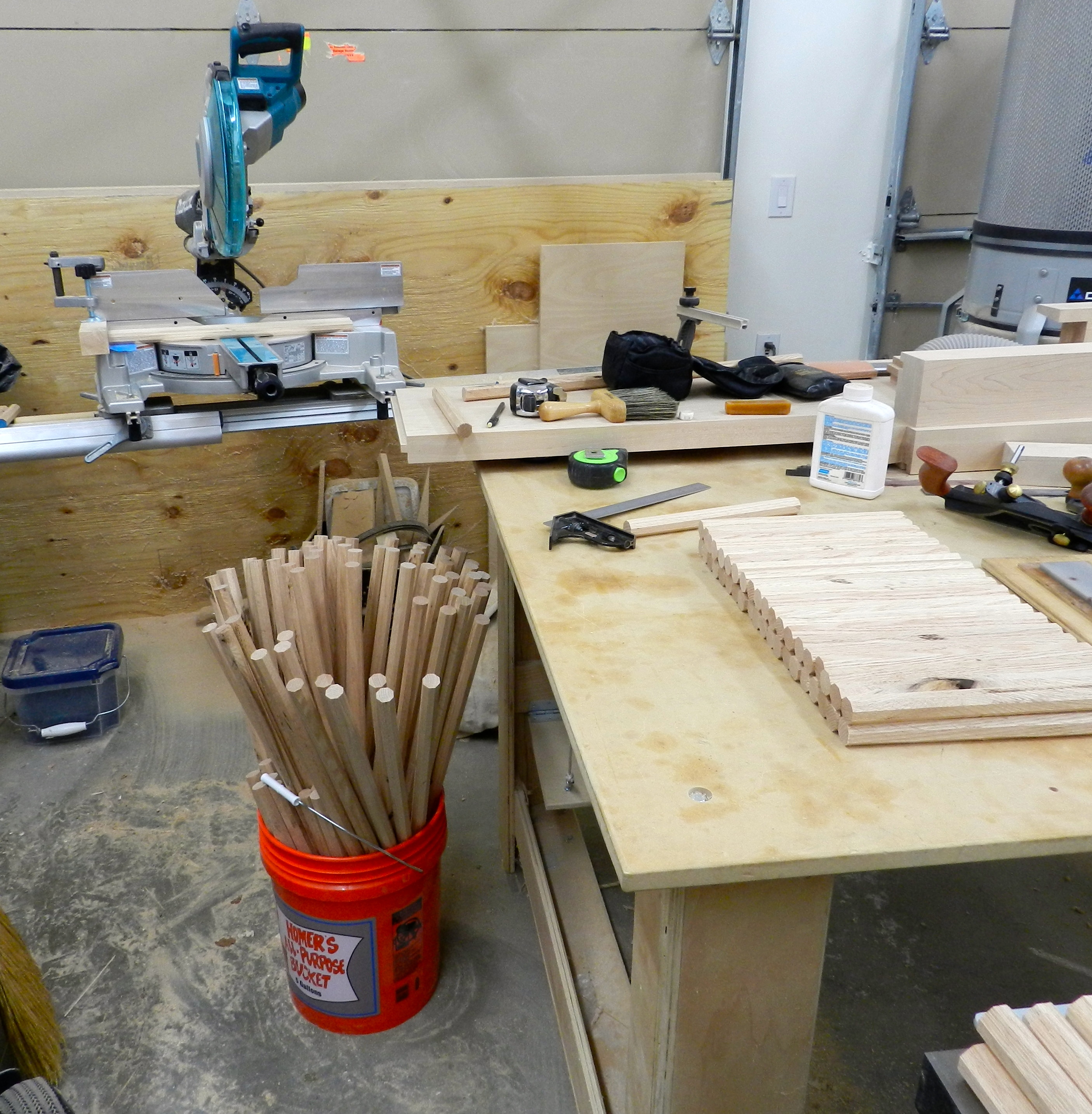
(4) Chopping several blanks at a time on the chop saw using a stop block

4.) I set a stop block on the chop saw at 10″ and gang chop (cut several at a time) for the sake of efficiency (See photo 4)

248 Oak Treenails and 166 Hard Maple Try Pins
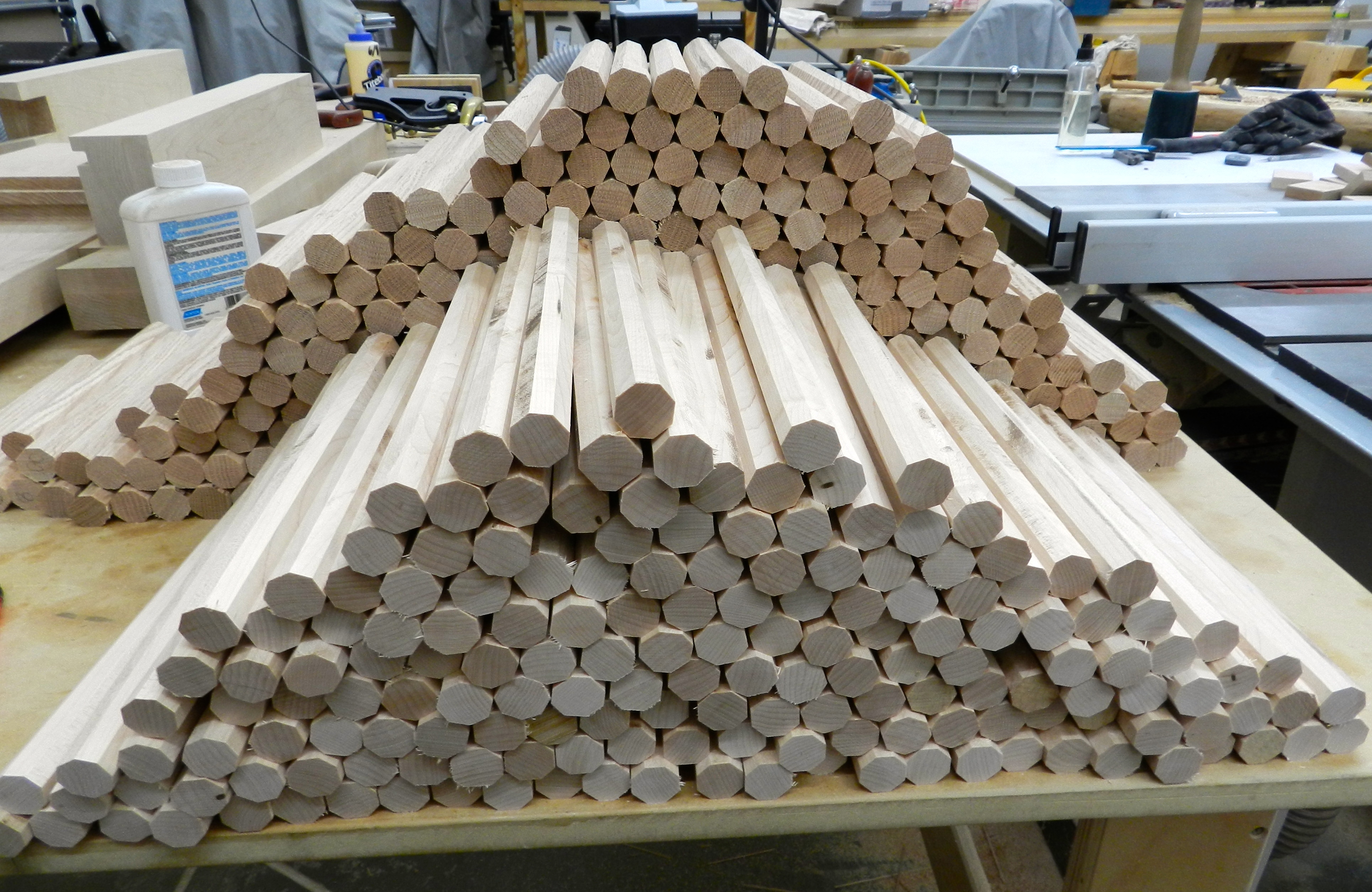
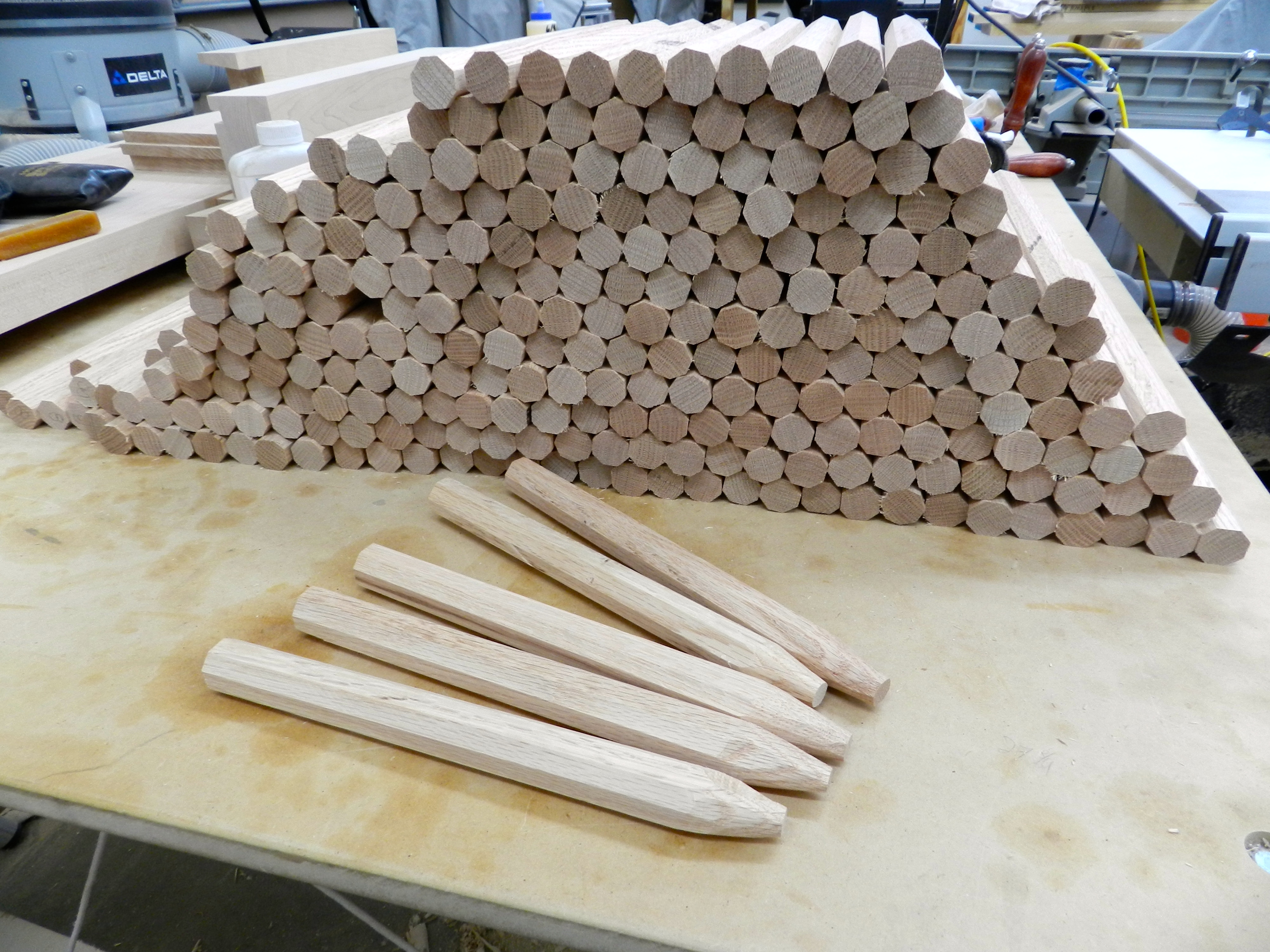
(5) 248 Oak Treenails and 166 Hard Maple Try Pins

5.) At this point you’ll quickly see how many pin blanks it takes to make even a modest building. (In this case a 12’x24′ large shed/small barn) (See photo 5)

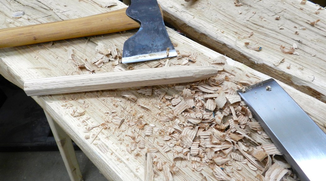
Using the hewing bench, carpenter's axe and timber framing chisel to taper the ends of each pin
(6) Using the hewing bench, carpenter’s axe and timber framing chisel to taper the ends of each pin

6.) Now it’s over to the hewing bench to taper the leading ends of the pin blanks. I usually rough off the wood with my capenter’s axe and touch things up with a timber framing chisel. I find it helps to get the cut started with the tool and bang them both (peg and tool) in unison on the hewing bench. The downward momentum drives the tool through the wood with a minimal expenditure of energy — important when you have a few hundred of these to complete.

Completed pins
(7) Completed pins

7.) I usually taper the first 2″ or so of the pin. You do not need to be overly concerned with trying to make the pins look like a sharpened pencil. You just need to knock off the corners to help guide the pin through the draw-bored joint.  Anything beyond that is to suit the design aesthetic you are going for. (Some folks will want to cut the ends off a pin in the house, so all the more reason to only do what you need to do with them)

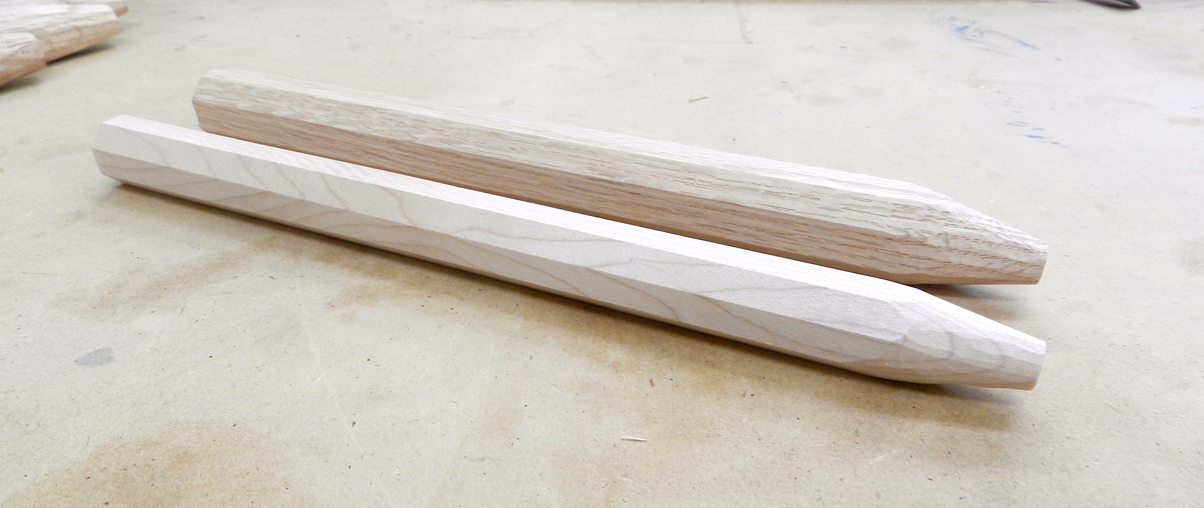
Foreground -- 3/4" Hard Maple Try Pins; Background 7/8" White Oak Treenails
(8) Foreground — 3/4″ Hard Maple Try Pins; Background 7/8″ White Oak Treenails

8.) Sit back and enjoy your work. Take a deep breath and repeat steps 1-7 all over again to make try pins. Try pins are slightly thinner pins used when test fitting your timber frame. I make them from hard maple for two reasons — I can visually differentiate them from the oak and the smooth hard maple is easily removed when the test fitting is complete. For this frame using 7/8″ Oak pins I make the try pins from 3/4″ hard maple stock. They are made the same way as their larger brethren.

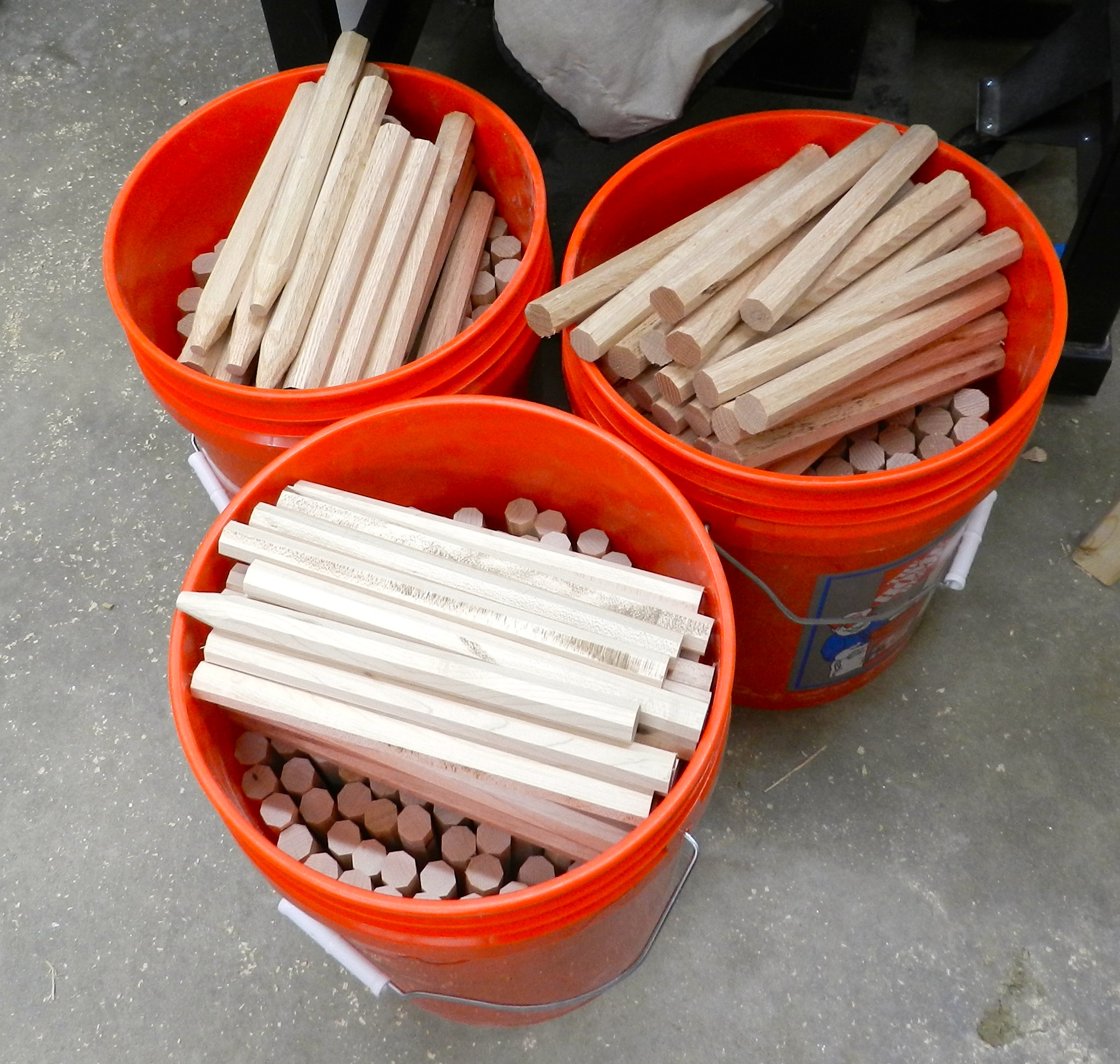
Full buckets of pins

Why are they octagons?

By making a 7/8″ octagon pin and driving it into a 7/8″ round hole the corners will bite into the wood and keep the the pin securely seated.  (The diagonals across the 7/8″ octagon are slightly longer than 7/8″.) This is why you want to use smaller try-pins during test fitting, this way you are not deforming/stretching the holes before the frame is raised.

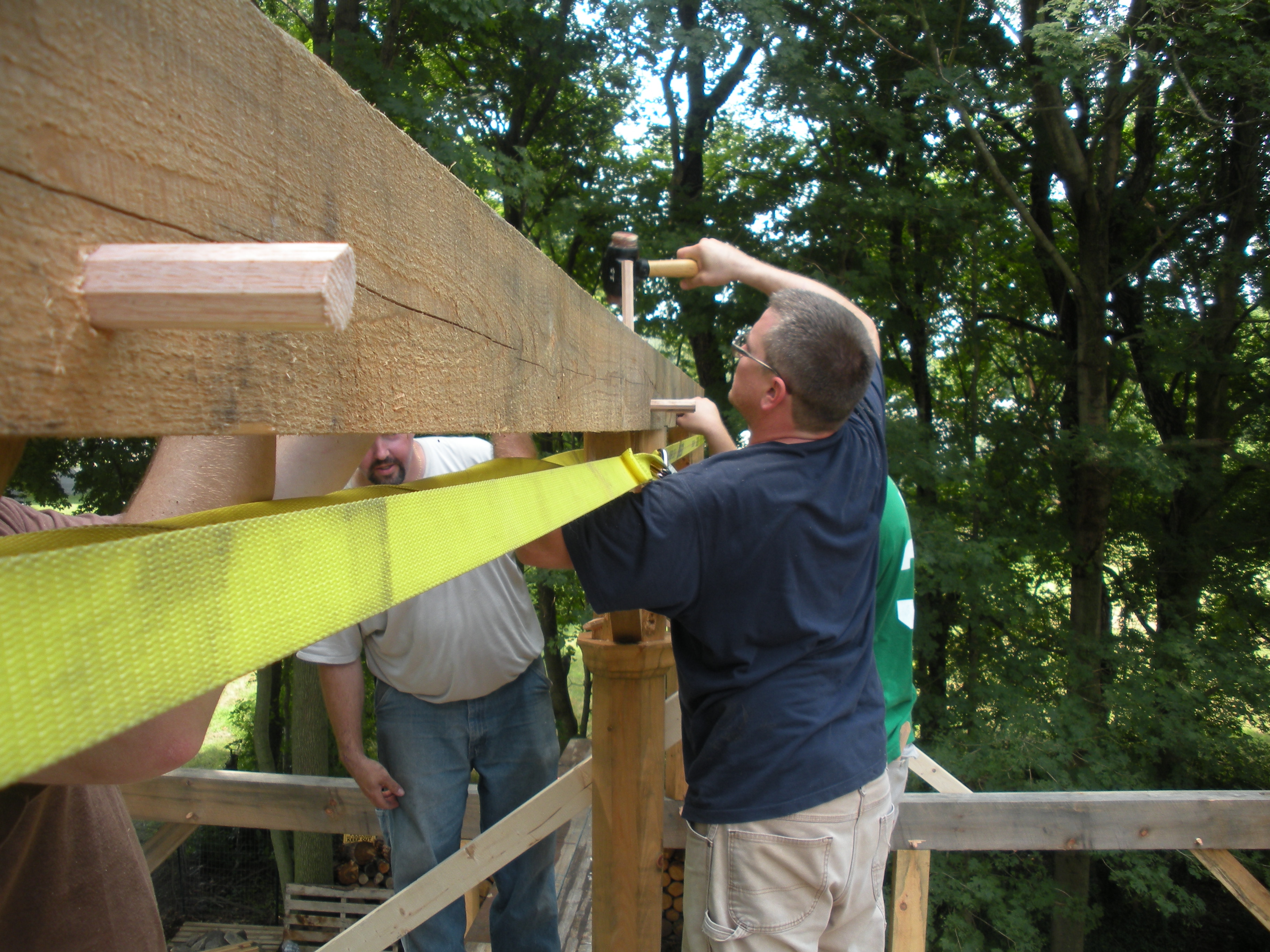
Driving in the pegs
Driving in the pegs

Tips for a high quality timber framing pin:

  • Use kiln dried pins with a green wood frame. Use green pins with a dried frame
  • I use most often use White Oak pins with green Eastern White Pine frames
  • I use Hard Maple Try Pins during test fittings (try pins should be 1/8″ smaller than your final pins)
  • Octagon your pin stock so that it properly bites into the joint
  • Taper the ends of your pins so they will easily enter the draw bored joints
  • Don’t stress too much about the tapering
  • Avoid the machine turned pins — I dislike the look, the cost (~$2 each), holding power, fact that they are not historical etc
Many pegs in a timber frame

Where can I learn more about timber framing?

  • Join the Timber Framer’s Guild (www.tfguild.org) and read the many good publications they have
  • Read any of the books by Jack Sobon, Ted Benson or Ed Levin on the topic of Timber Framing
  • Take a class in timber framing at The North Bennet Street School (with Rich Friberg or me), or at the Heartwood School in Western MA

The next time you are in a barn or timber framed building I hope that you will take a moment to examine the pins holding the joinery together.

-Bill

Hewing Bench Revisited (Already)

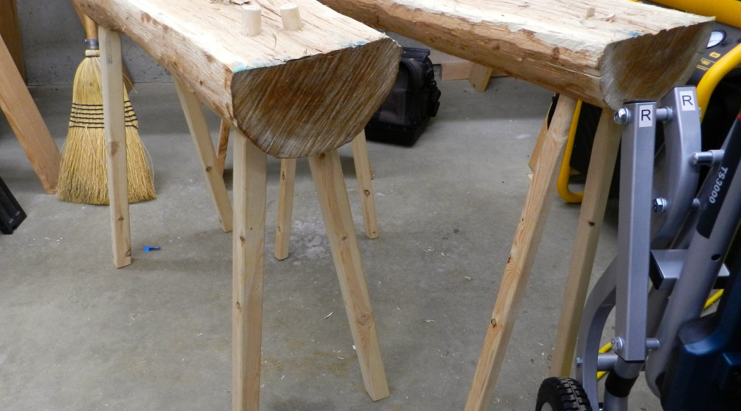
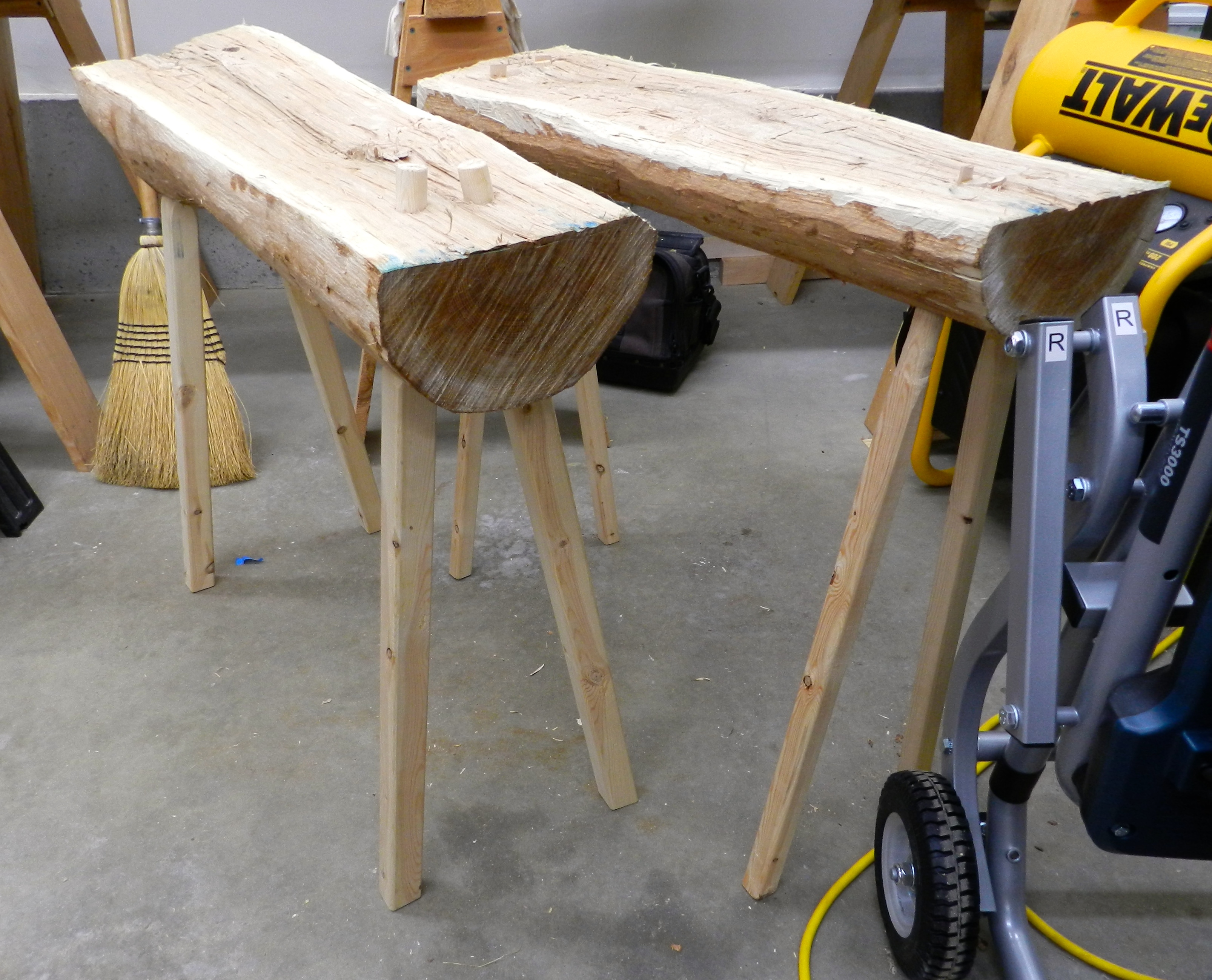
After living with my new hewing bench for a few weeks I finally got around to using the other half of the log. I’m glad things worked out this way as I made some modest improvements based on our time together.

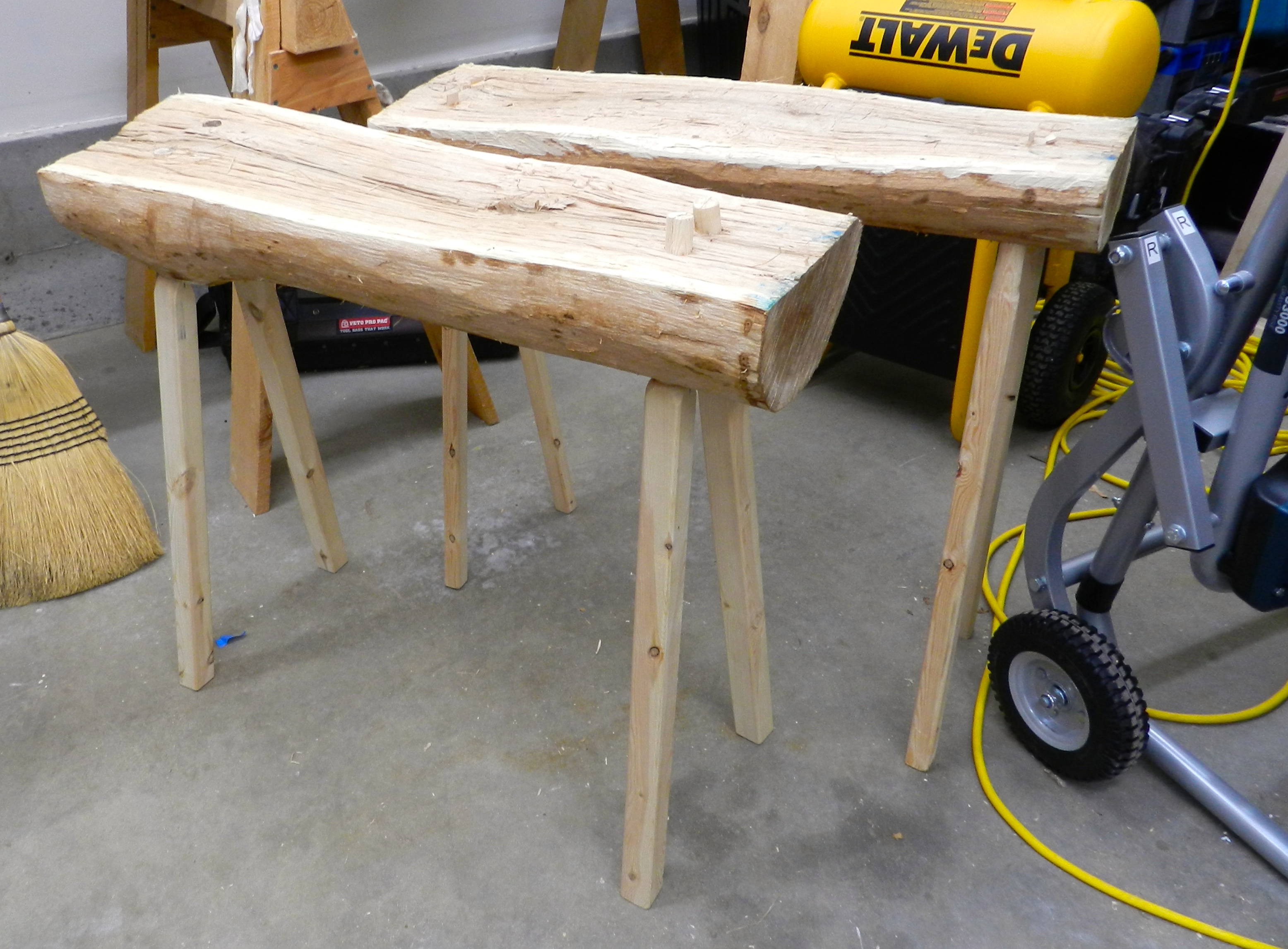
Original bench on the right, revised model on the left

The original bench was fairly solid — it could hold me standing on it and didn’t bounce around when I would strike it in a downward motion — but when I’d do something heavy and lateral I could feel what felt like a tiny bit of flex in the the legs.

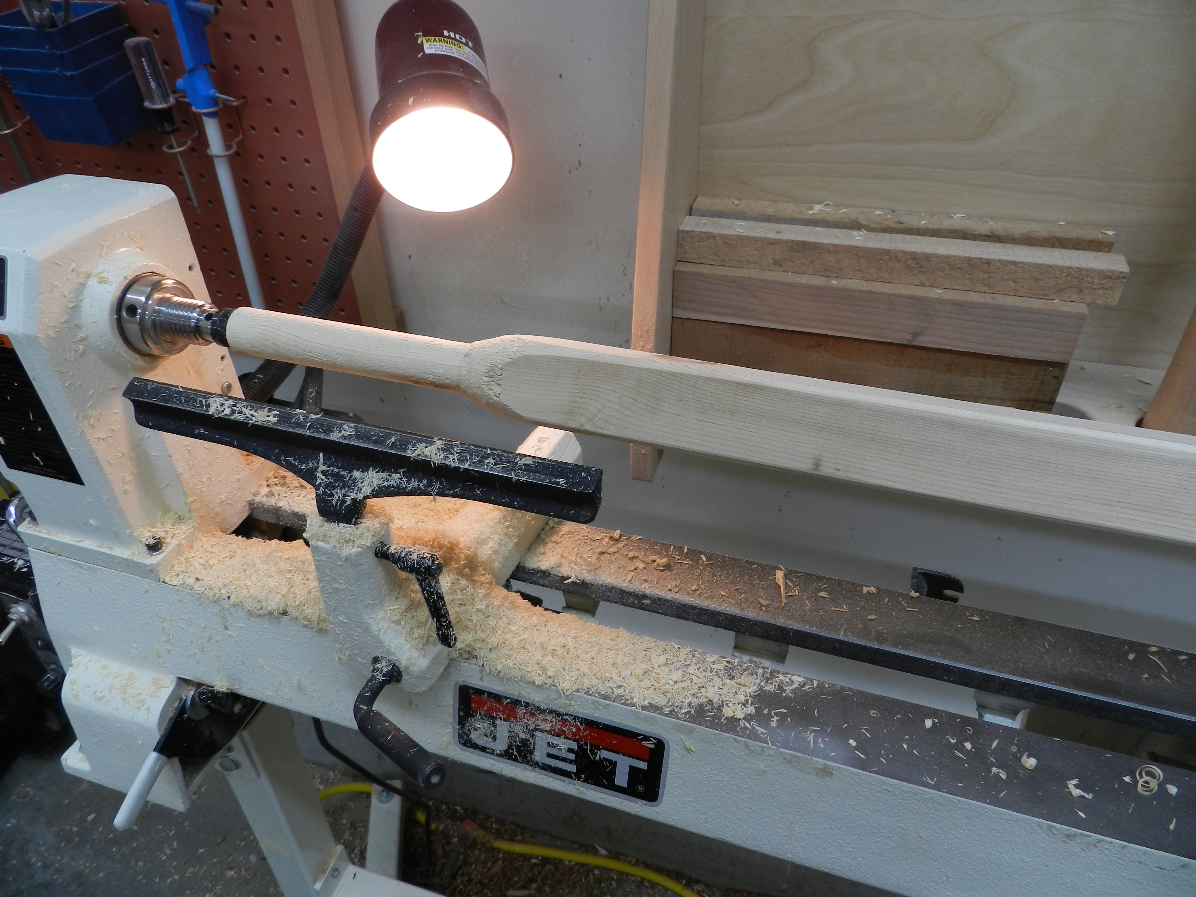
Turning thicker legs

At the time I ripped down a 2×3 to make the legs roughly sized to the 1″ ship auger bit which was the largest I had on hand, but I worried about the 1-1/8″ legs being too spindly. The mental image of the legs being too spindly haunted me, so for this second time out I decided to rectify that issue.

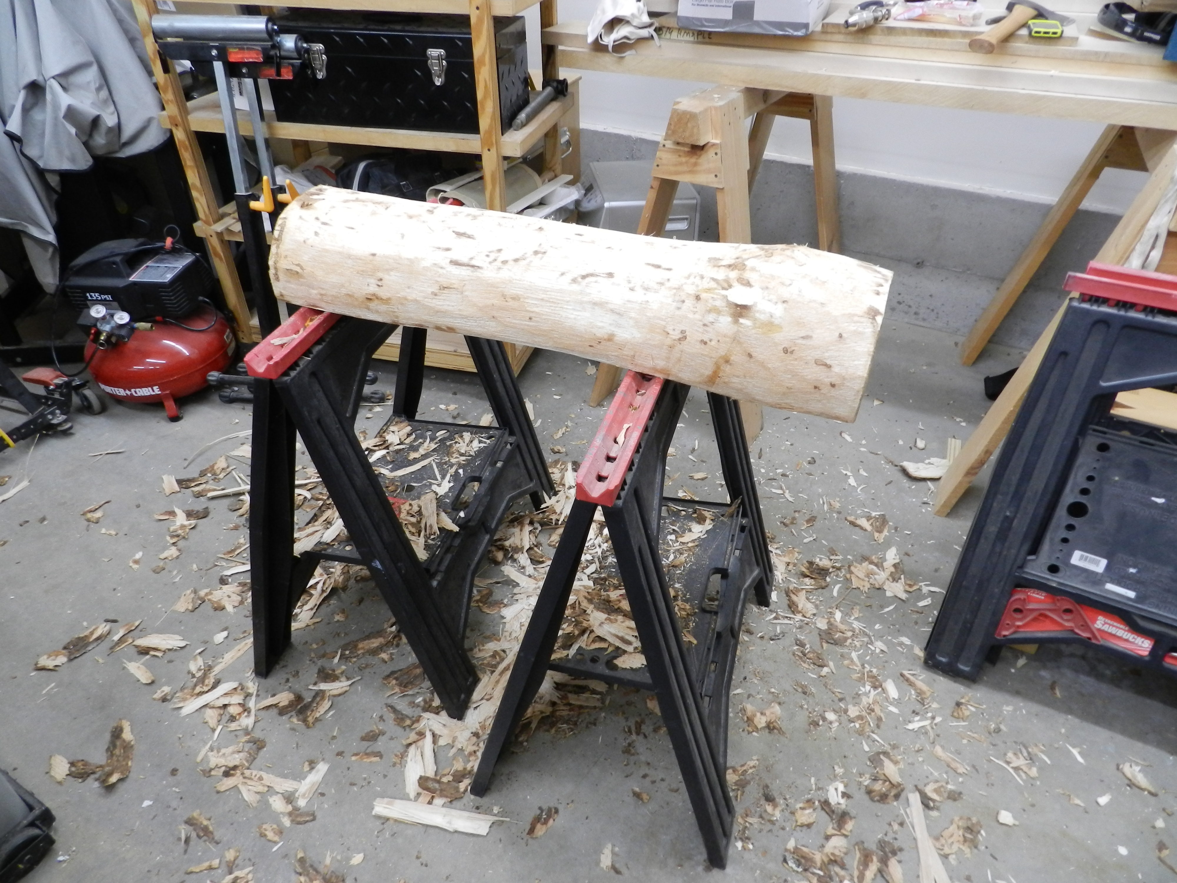
Removing the bark from the half log

Improvements:

  • Thicker legs (1-1/2″ square) with a more pronounced shoulders (this way the legs don’t add to any unnecessary wedging/splitting pressure and no matter how much hammering takes place on top of the bench the legs are maxed out in how deep they will go into the top of the bench)
  • Legs splayed in both directions to be that much more stable
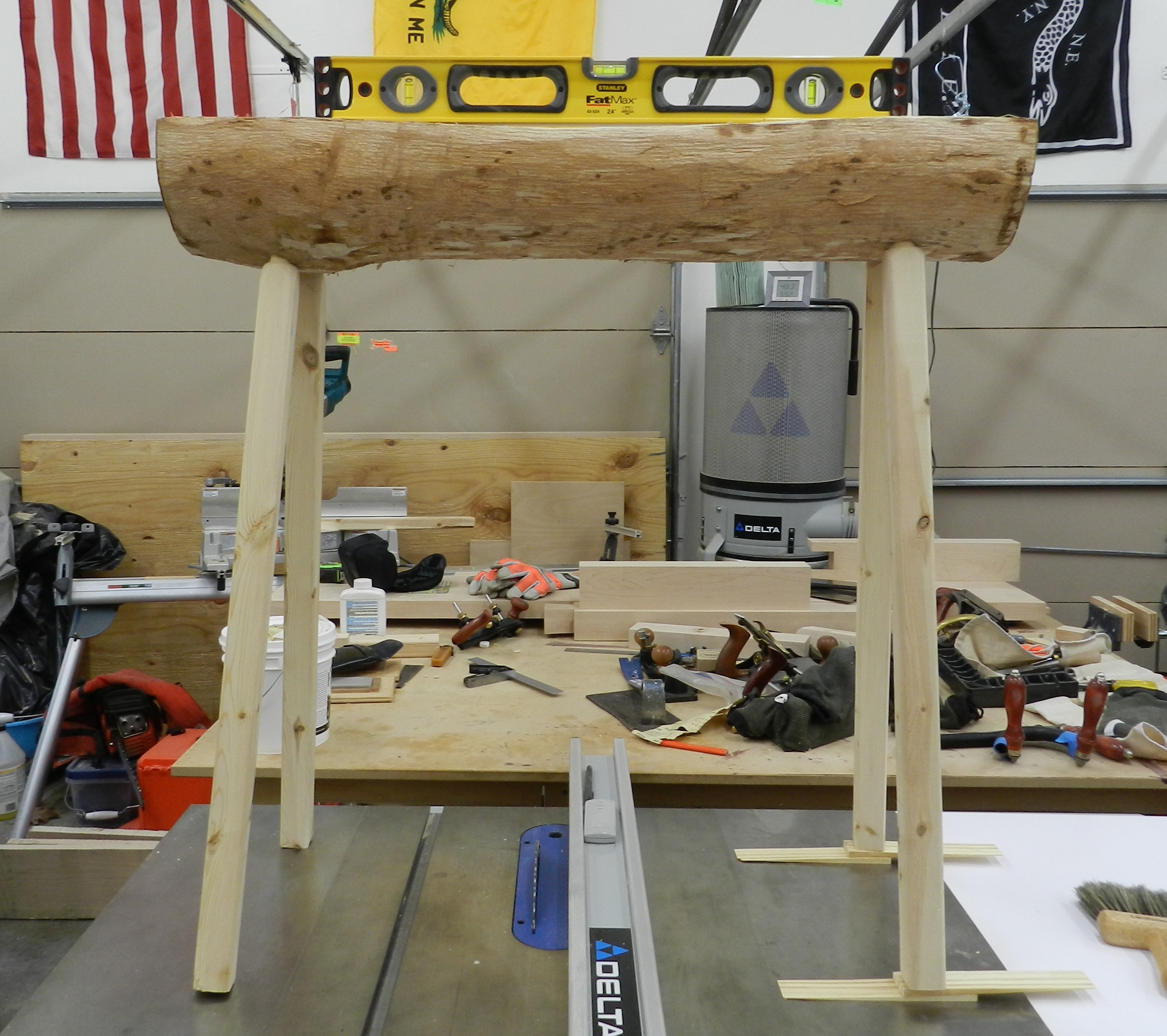
Leveling the legs
Leveling the legs

Beyond the modest improvements called out above, I otherwise built it the same way as the first hewing bench. (Wedged tenons, wax sealed end grain, leveled legs etc)

Completed benches. They can also work well as a pair of saw horses.

The Verdict:
The new bench is rock solid and will be a workhorse in the shop. The new legs are nice and stiff. Having a pair of these benches in the shop has already come in handy as you’ll see in the next post.

Take care,
-Bill