Category Archives: Modern Carpentry

26 Horses and 2 Ponies

The best saw horses cannot be bought in a store, you have to build them.  I’ve seen plastic saw horses bend and buckle under < 200 pounds of load.  I’ve seen 2×4 saw horses with sheet metal couplers deform and crush.

When I was a student at NBSS one of the first projects we completed was building a pair of solid wood saw horses that could meet the heavy demands of a preservation carpenter. The school would load them up with more material than I ever thought a simple horse could hold. I was so impressed with how well they turned out I built 10 more while I was there and they have served me well over the years.

28 horses out on parade

Right now as I build a 24’x30′ timber framed barn out in the yard I built another 28 horses to hold all the timber off the ground for sorting and working through the piles. The post below covers how I built these heavy duty horses.

For a large run of horses like this it is important to run through each operation like a small assembly line, though at times it can feel like a slog — after cutting 112 legs you become a master at optimizing all of your operations.

Large pile of green eastern white pine ready to go.

The wood of choice is green eastern white pine we buy from a local sawyer/lumber company. (Copeland And Sons Lumber).  The beams (the work surface of a horse) is cut from a 4x4x12′, the legs are made from 1x6x12′ boards and the gussets are made from 1/2″ CDX plywood.  Buying rough green stock like this from a sawyer helps keep the price per horse reasonable and the wood is full size, not nominal, so my 4×4 is 4″x4″ when I get it.  I estimate that they cost me < $10 each in terms of materials.

You can see how much moisture is still in the 4x4s

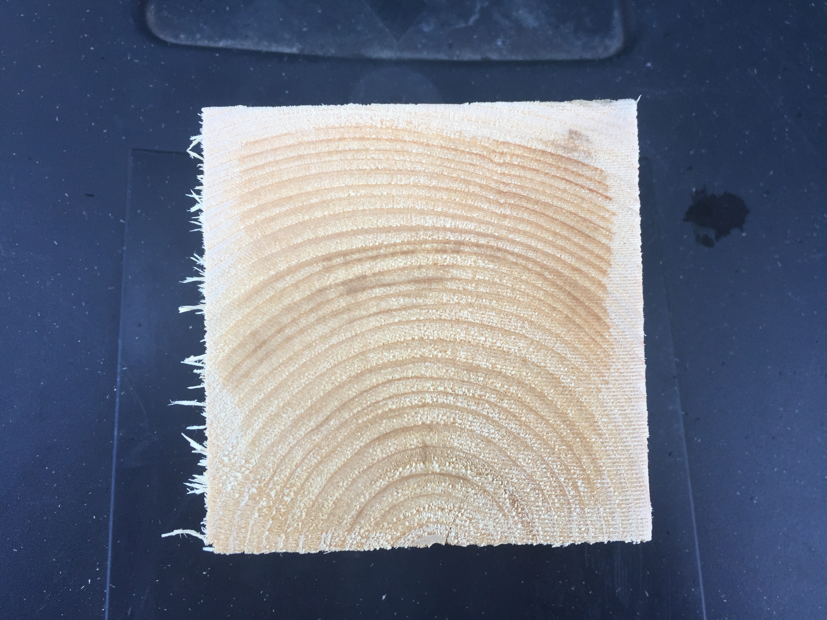
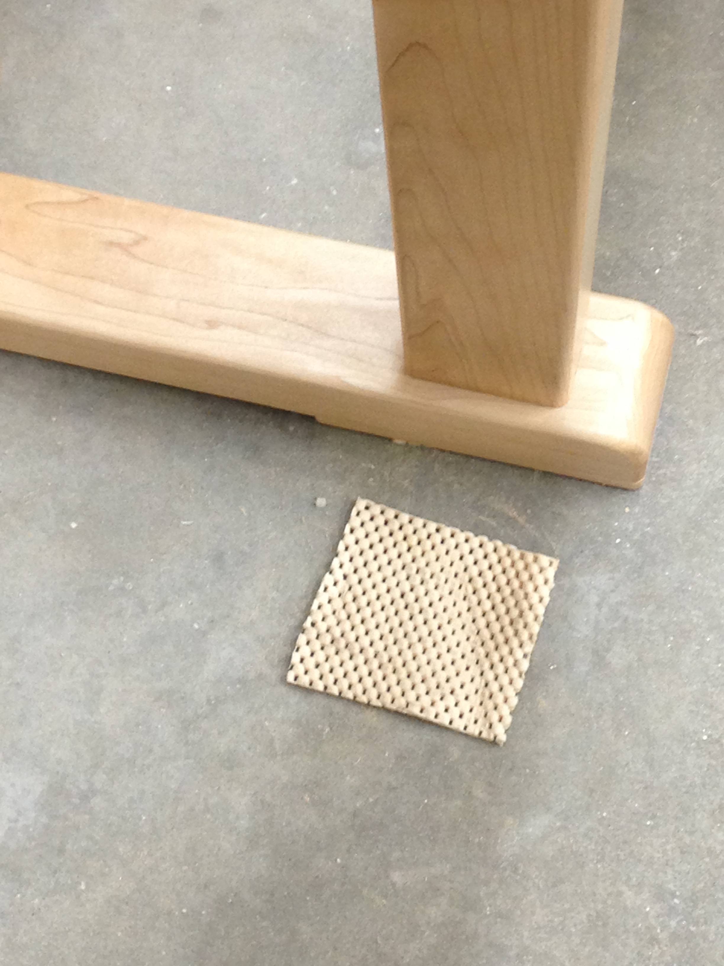
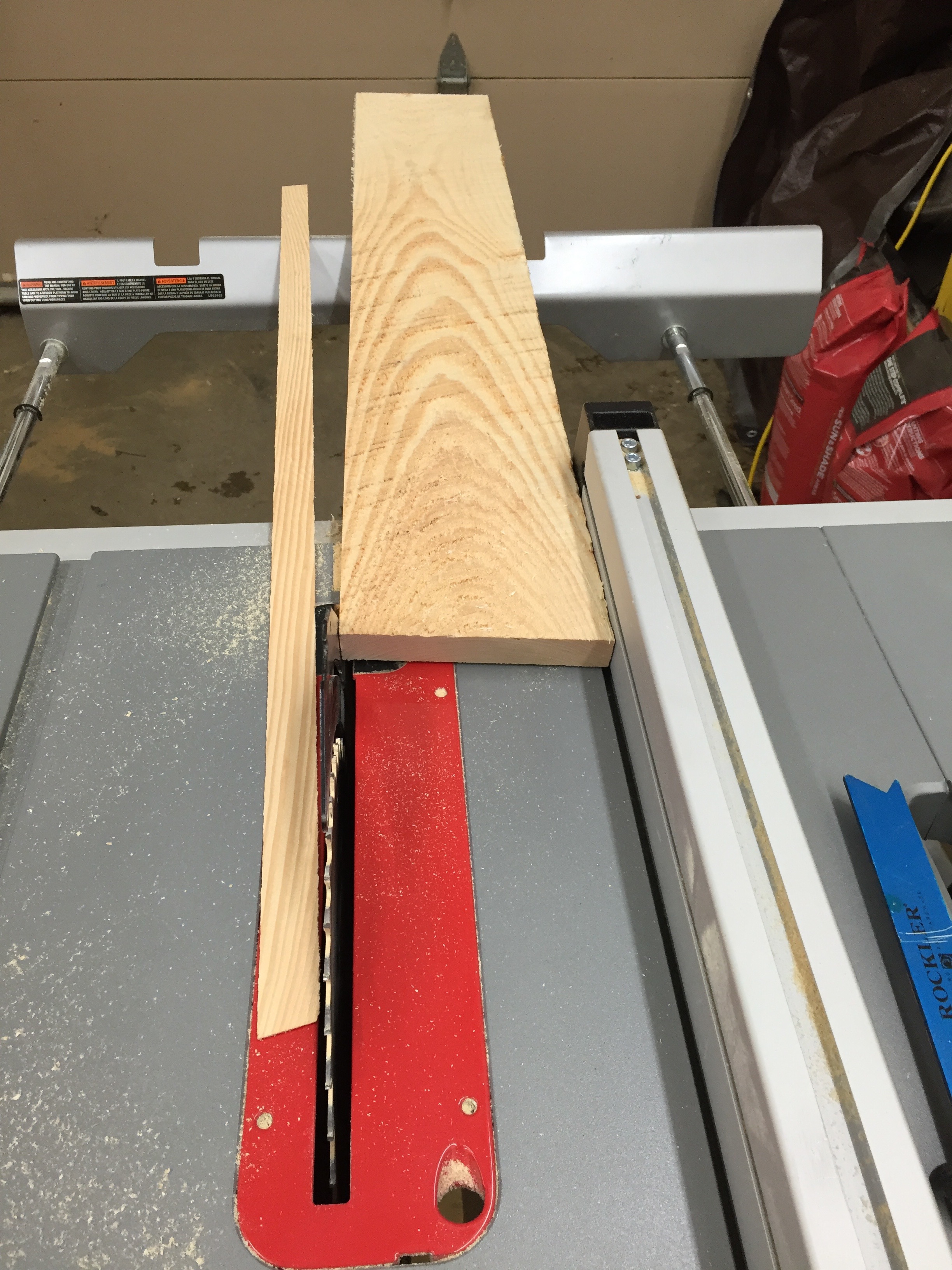
A note on working with green lumber, for horses or timber frames or similar projects — this wood was a tree possibly only a day or two before I get it, so if you use a power tool you may get some water spray on you. Be warned. Also make sure you wipe down and oil your tools appropriately so they do not rust. In the photo above you can see the outer 1/4″ or so that has dried a bit vs the wet center on this fresh cut off piece.

Stack of cut beams
Stack of cut beams

I start by cutting the beams to 36″ long. I then cut a 12 degree bevel on two sides. If your table saw cannot cut a full 4″ on an angle you can cut as much as you can, snap off most of the waste and then use a jointer or portable power planer (like 3-1/4″ Makita Door planer) to even out the side.

I also stamped my name into the end grain of each beam with my name stamp. It makes it easy to tell my horses apart from say another friend from the school.

Beam and gusset with dimensions. I also used my namespace on the beam end grain.

Next up I ripped my 4×8 sheet of 1/2″ CDX plywood into ~4″ wide strips. I then took a second pass on each strip with the blade set to a 5 degree angle. This allows the gussets to nestle up tightly against the beam during final assembly.

Cutting compound angles for the legs. 5 degrees and 12 degrees.

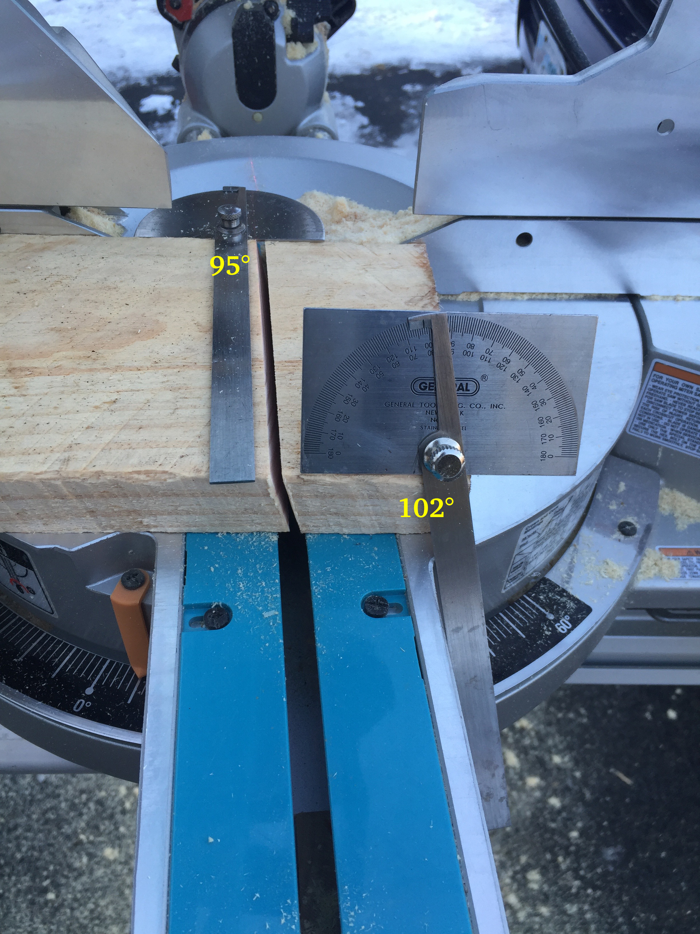
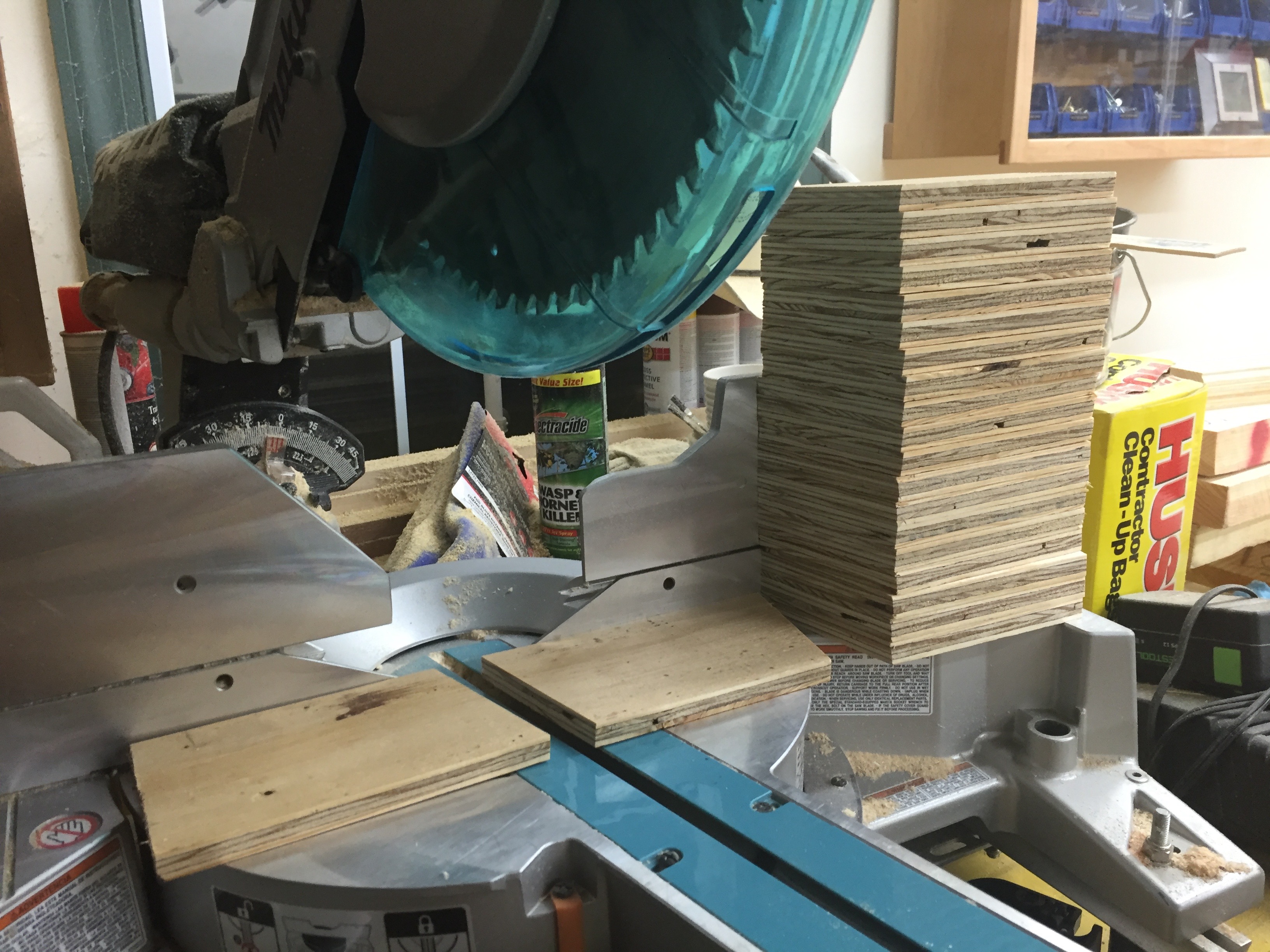
Next up I cut all the legs. I set the compound miter saw to cut at a left tilt of 5 degrees and a right rotation of 12 degrees. (See image above). The long side of each leg was cut to be 34.75″ long.

Ripping the legs to a consistent width

With all the legs cut I ripped the rough edge off of each board, then ripped the other side so all the boards landed at a consistent 5.5″ width.

Stacks of cut legs
Stacks of cut legs

You don’t have to plane the boards to thickness if you don’t want to. Leaving them as thick as possible added to the strength and I am not thrilled about passing green wood though my cast iron tools and into my dust collection system.  My site chop saw and portable table saw both have aluminum tops which deal better with the wet wood.

112 legs ready to go

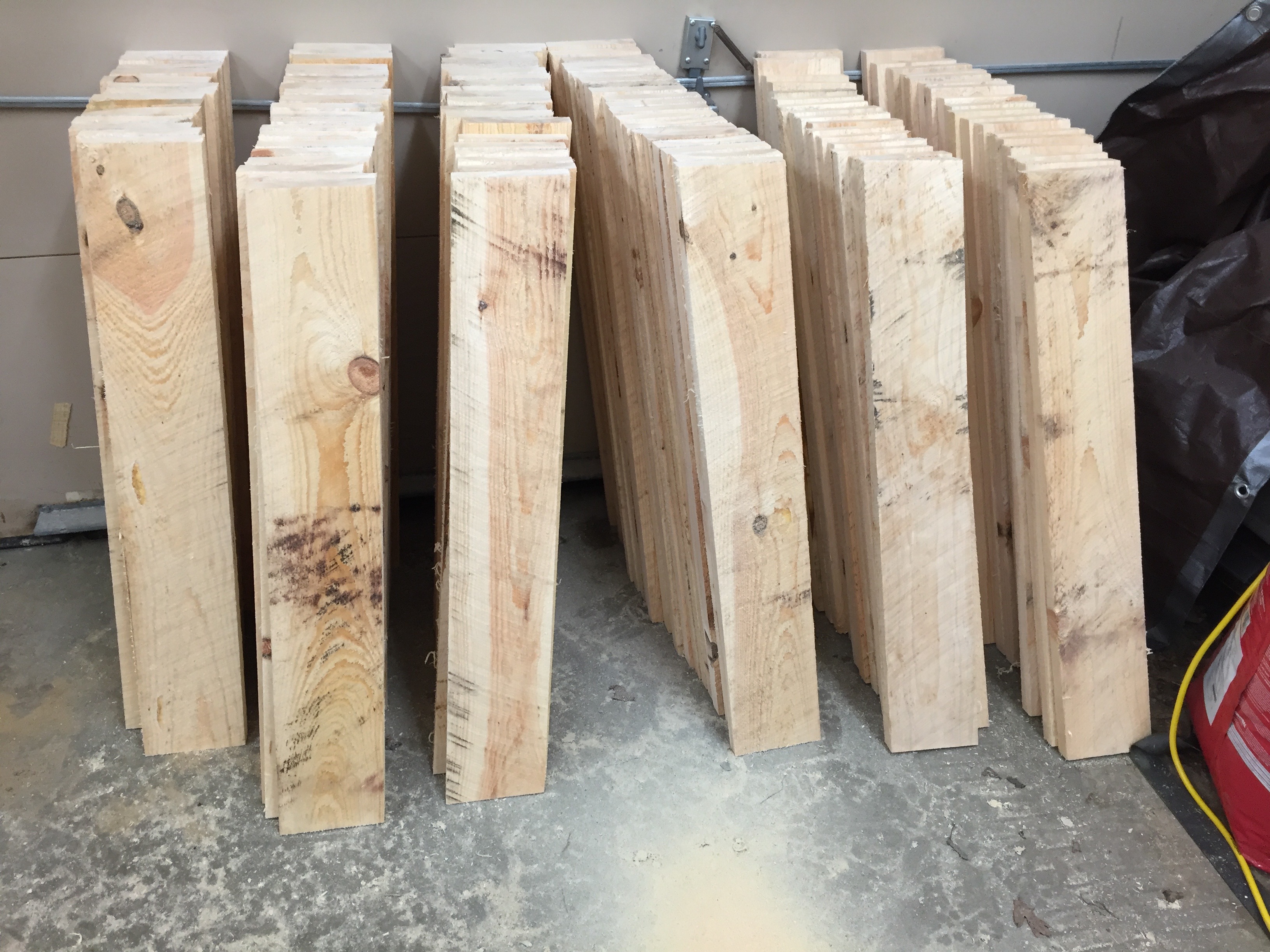
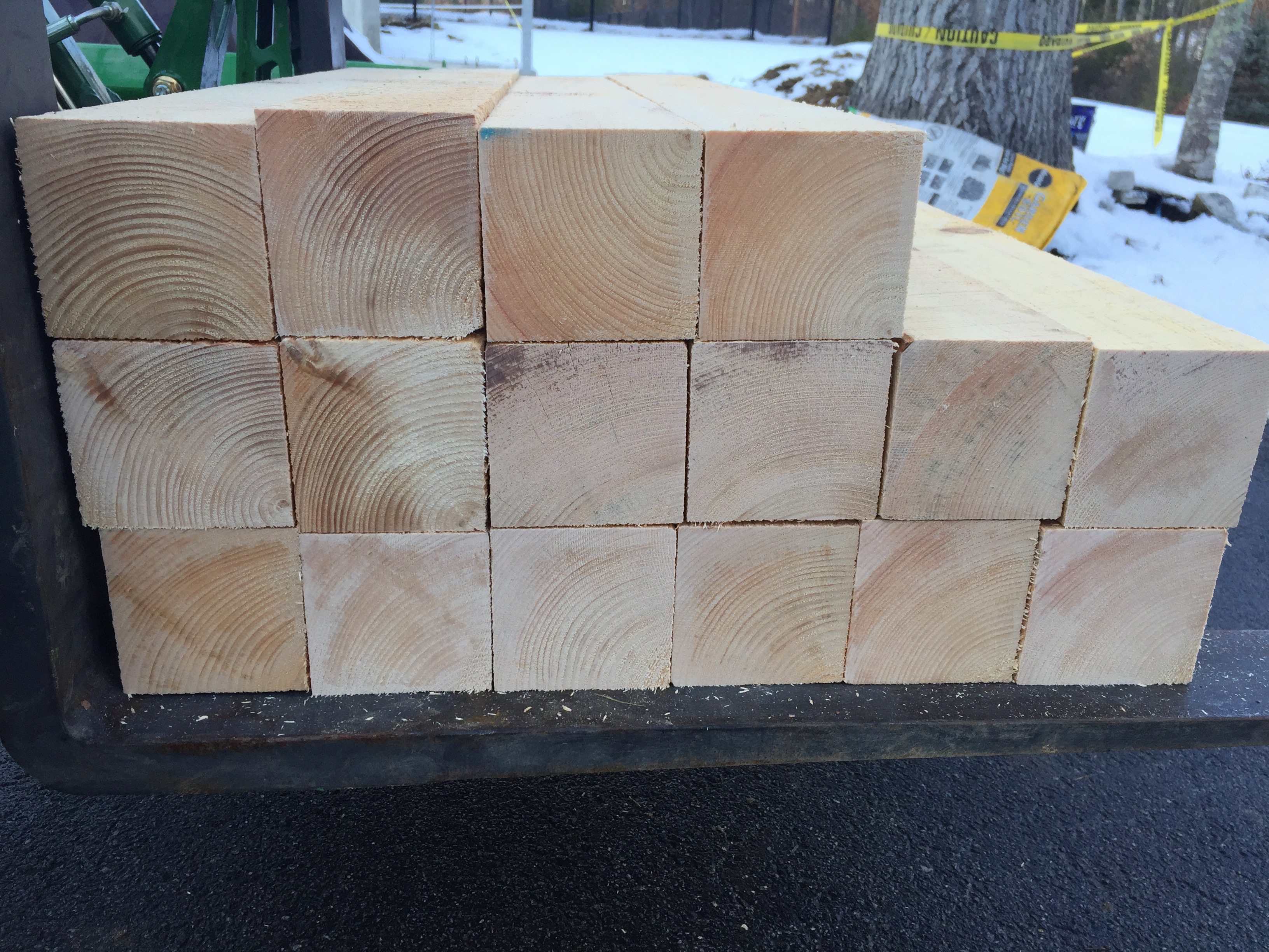
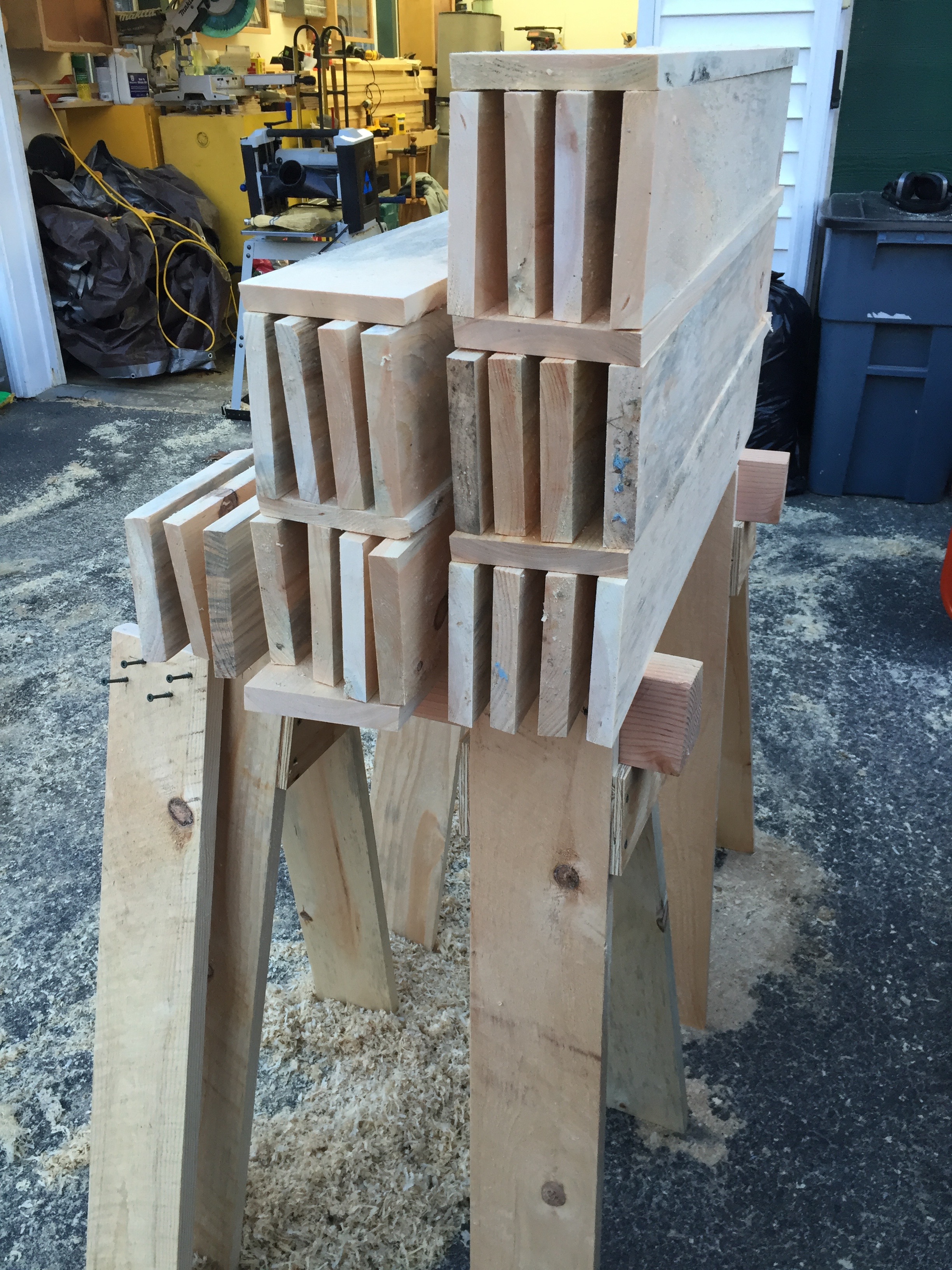
All the legs are the same, though above I stacked them to make sure I had a correct number for all the horses I planned to build.  I also used a low angle block plane to break all the edges on the boards since they will be handled many times over the years and you don’t want any splinters.

Stacks of cut legs and beams back in the shop

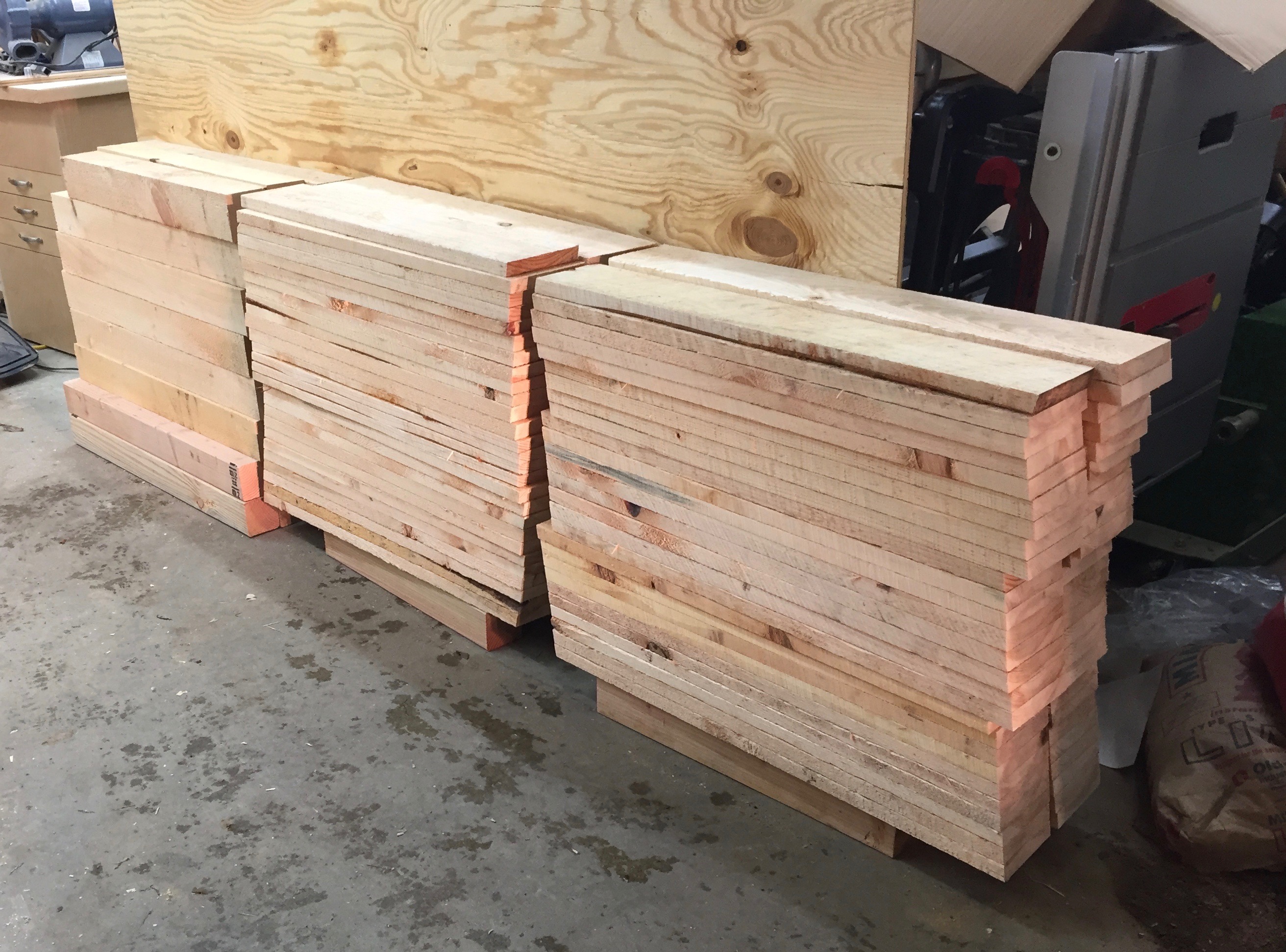
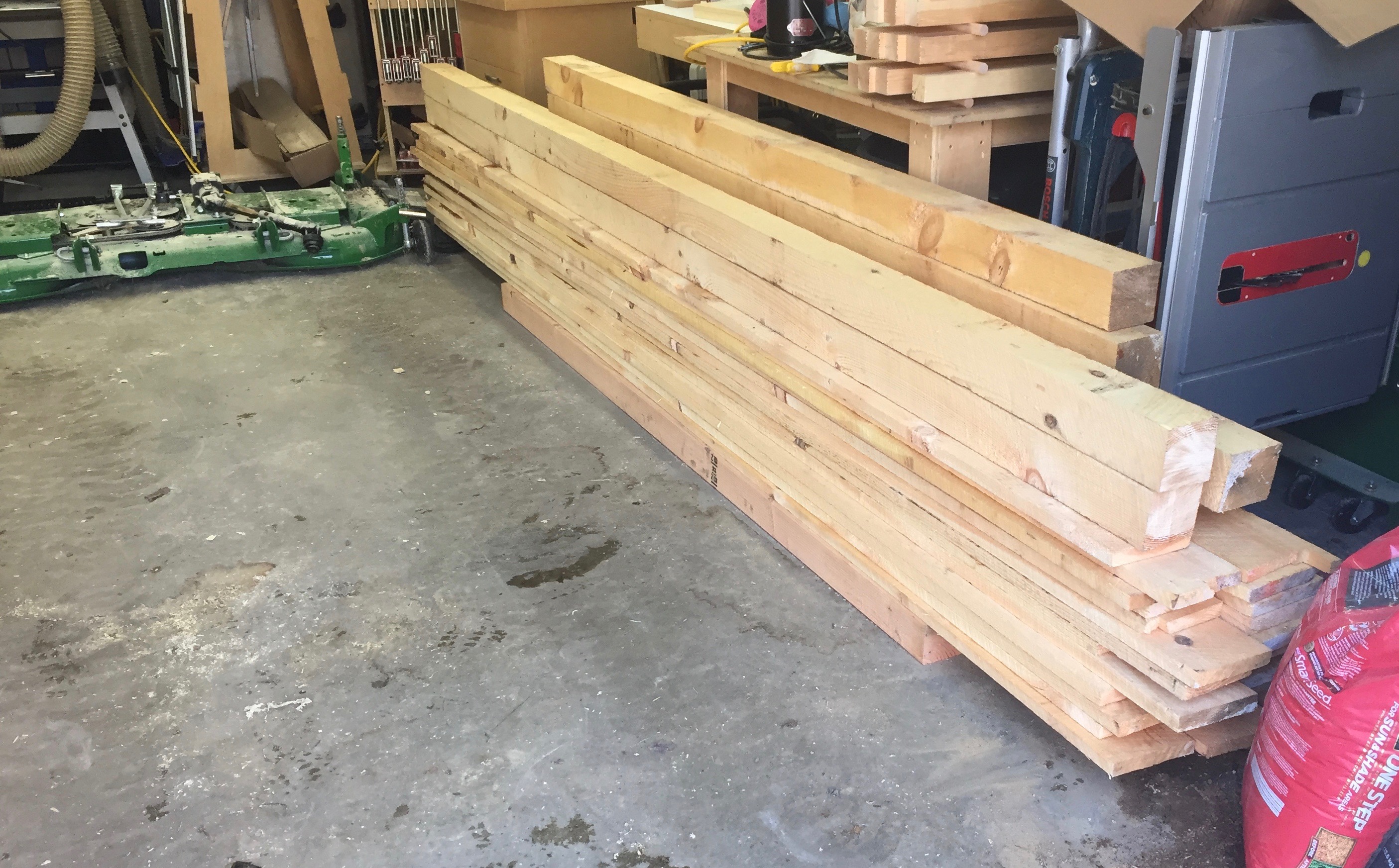
I then brought my wood into the heated shop as we were getting some snow and stacked them as you see above. This was a big mistake as I’ll describe later. I planned to be out there the next day but with snow and a baby in the house they sat out there for a week. If you bring sopping wet/green wood into a heated shop, make sure you sticker them so air can flow around all the edges and the wood can dry evenly.

Layout for the 2" ceramic star drive deck screws.
Layout for the 2″ ceramic star drive deck screws.

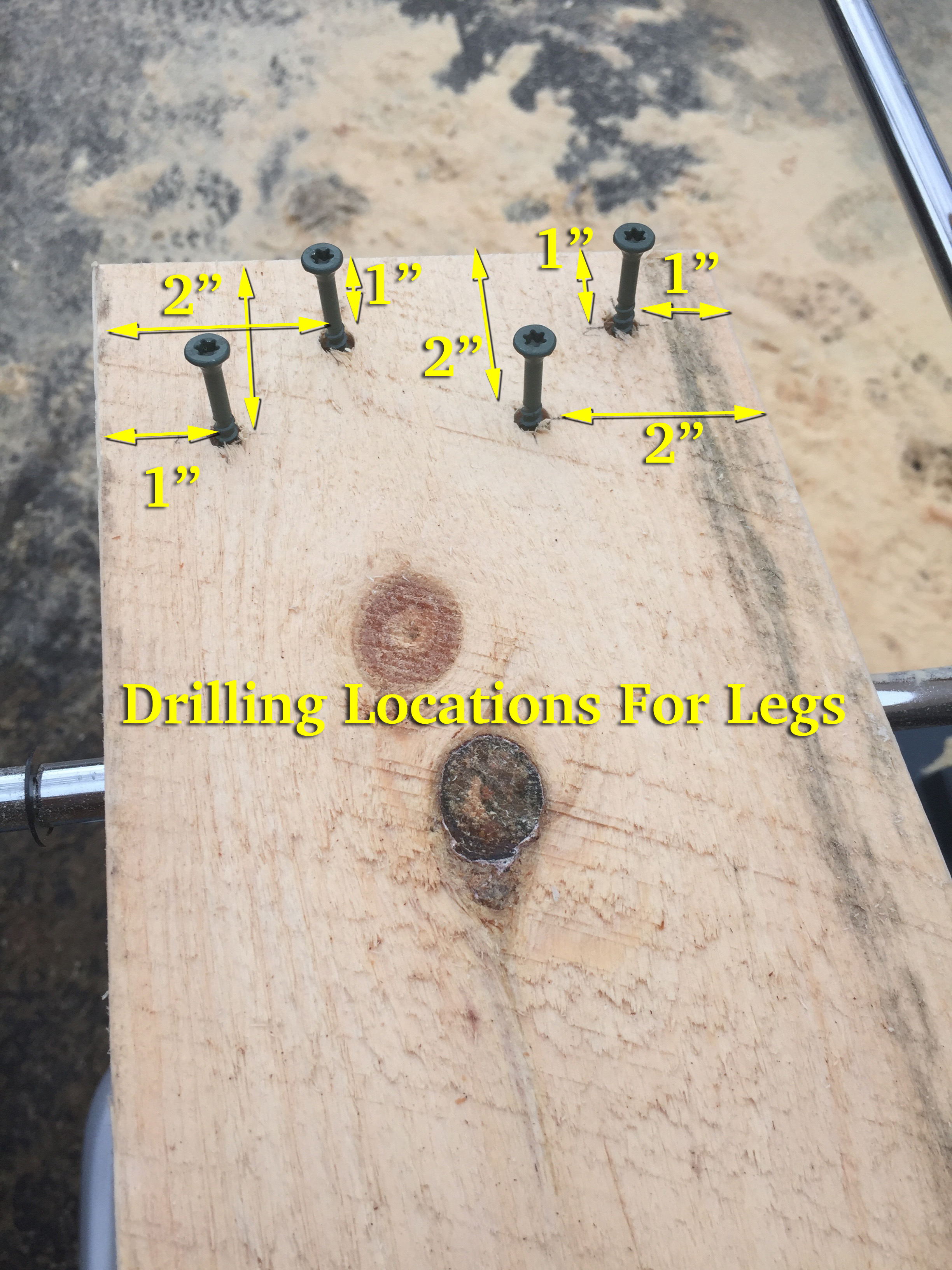
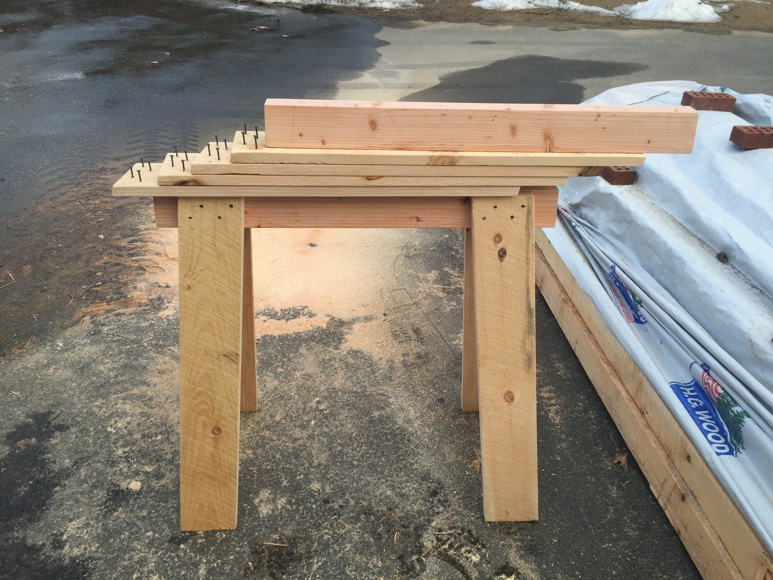
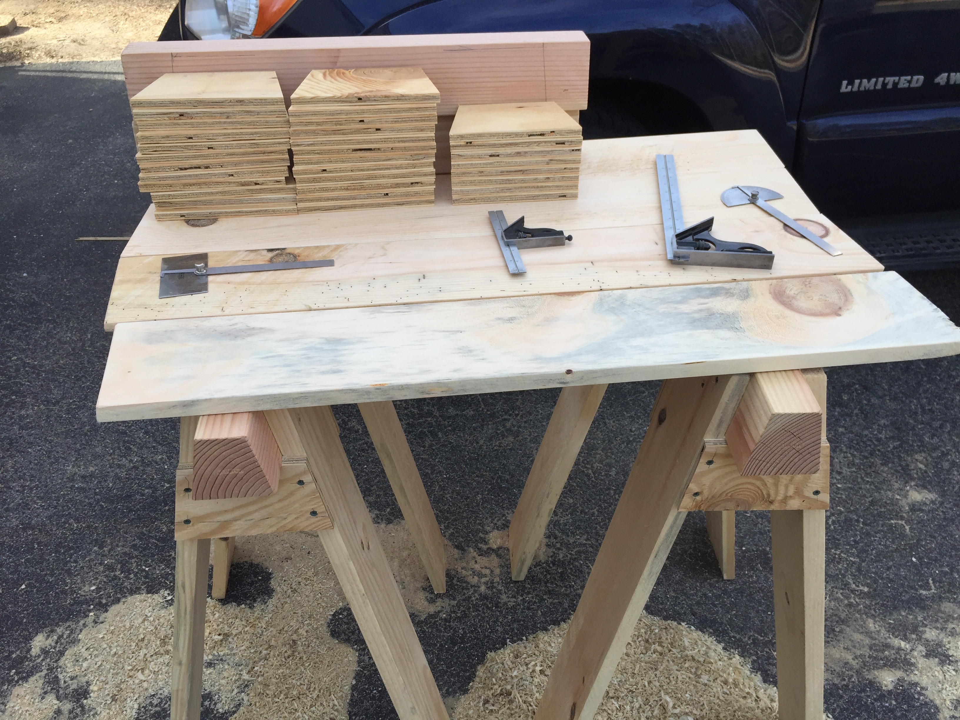
With all the legs cut I started to layout for the screws. I grab two combination squares and set one to be 1″ and set the other to 2″. This allows for fast/efficient layout. (see above image). Each of the screws is either 1″ or 2″ from the edge or top of the board. The screws are staggered to help avoid splitting the wood. I used DeckMate 2″ ceramic coated deck screws that have a nice thick shaft and are rated for outdoor structural use and do not rust. Do NOT use drywall screws on this sort of project, they are far too weak and not meant for the outdoors. One 5lb box of #8 2″ screws was enough to attach all the legs. After layout I pre-drill each of the holes and start the screws into the boards — this makes it a lot easier to assemble the horse later on.

Laying out the beam. 5 degree angle is set in 2.5" from the end. The top of the legs should be 1/4" below the top of the beam.
Laying out the beam. 5 degree angle is set in 2.5″ from the end. The top of the legs should be 1/4″ below the top of the beam.

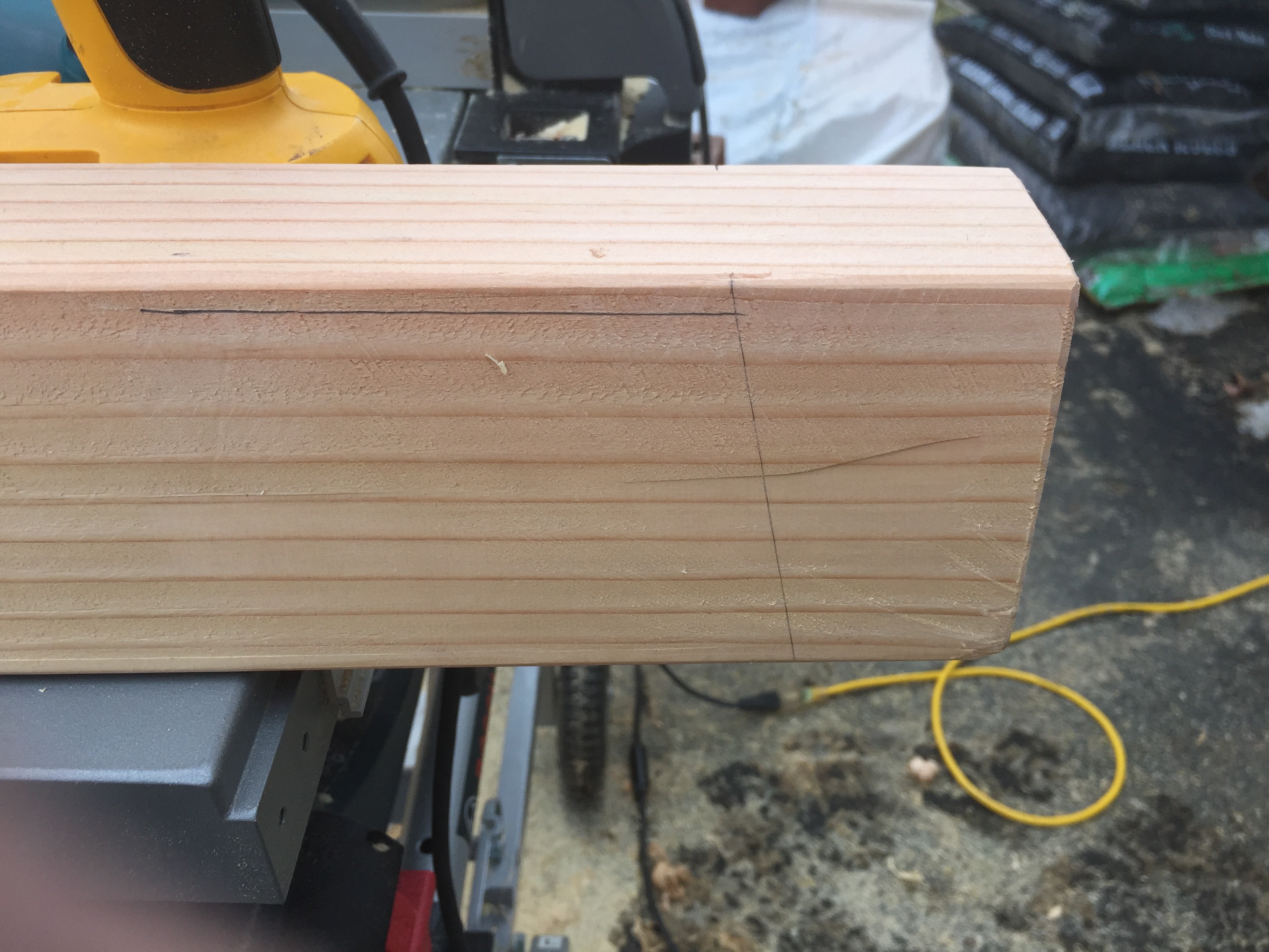
For the beams I make a tick mark 2.5″ in from each end on the top edge of the beam. Using a protractor I make a 5 degree line down the side of the beam — this splays the legs and gives use  nice stable horse. Having two protractors on hand is nice as I have one set for the right and one set for the left. I then set a combination square to 1/4″ and make a line along the top edge of the beam — this allows me to line up the legs during assembly. I also broke all the edges with a block plane.

Another horse ready to be assembled

Early on I made a few pairs of saw horses to work from and did the majority of the horses as a large run.

Attaching the legs — I added one leg at a time, usually only sinking 2 or 3 of the pre-started screws into the beam. I add one leg, then add the second leg on the same side of the beam. This makes it easier to stand the horse on those two legs and add the third leg. When adding the 4th leg you’ll want to make sure all 4 legs are properly resting on the ground. If your horse wobbles this is your chance to adjust the legs. When the horse is standing the way you want you can sink the rest of the screws on the legs. When using an impact gun you don’t want to sink the screws any further into the wood than you absolutely have to. Ideally the screw heads should come to rest in the same plane as the surface of the wood, but green pine can be a bit soft so some of them may go deeper before they have enough grip to pull the leg tight to the beam.

Mass producing gusset plates.

With a beam and set of legs ready to go and standing nicely you can take a plywood gusset blank, bring it over to the partially assembled horse and trace where it meets the legs. Ideally the gussets should not stick out farther than the legs, otherwise they might catch on things. Making them say 1/32″ inside of the surface of the legs is what I shoot for. Using that traced piece I cut it and label it as a the template and use that for laying out each of the subsequent gussets

Important Notes About Gussets:

1.) When cutting the gusset the beveled end is always ‘up’ on the installed gusset — it mates nicely to the underside of the beam.

2.) When installing a gusset make sure the 5 degree bevel is facing the correct way so that it rest tightly up against the beam.


Impromptu work table

With a few horses pressed into early service I was able to make a makeshift table that allowed me to layout/mark all the of the gussets. Each one is secured with 4 screws. I made a mark for each screw to be 1″ down from the top or the bottom of the gusset and centered on the thickness of the leg, so for most that would be ~3/8″ in from the mitered edge. I turn a horse on its side and place the marked gusset where it is going to go. I then pre-drill the gusset in place and drive the screws. I used #8 1-5/8″ Deckmate Ceramic Star-drive screws and again a 5lb box was enough for this project.

Each horse required 16 2″ screws and 16 1-5/8″ screws.

Saw horse with dimensions.

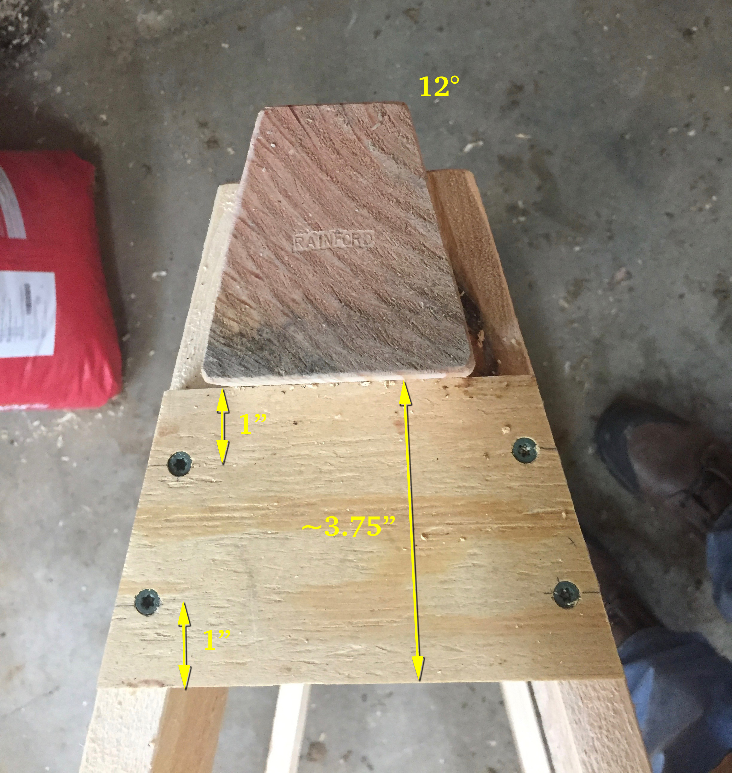
And now we have a completed horse! The image above has some more dimensional information for quick reference.

Lunchbox planer getting a workout

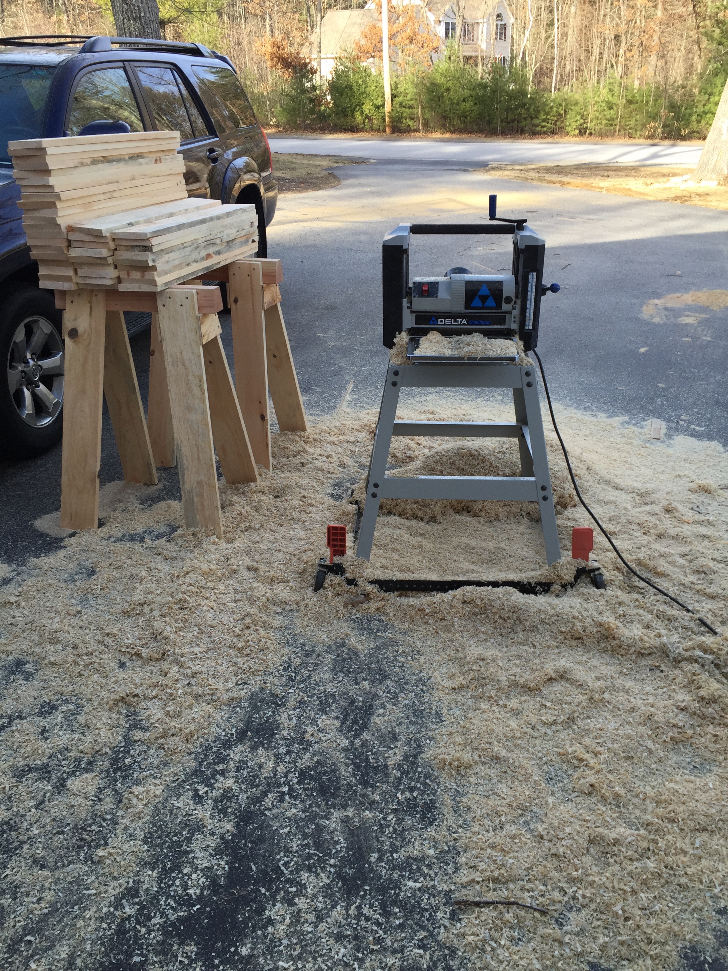
Now back to that mistake I mentioned earlier. By leaving the cut wet boards tightly stacked a mold/fungus quickly bloomed on half of the boards. I have a lot of allergies so I didn’t want to handle those boards any more than I’d have to, and it was unsightly, so I suited up and with my dust mask and fed them through my lunchbox planer. I also didn’t use my dust collector as I don’t want that wet fungus living in my filter. I planed the rough boards smooth and stickered them up to dry in the sun as I worked on other horses.

Letting the legs air dry a bit

That little mistake accidentally created ‘Denim Pine’ — pine boards with a blue tint that results from that fungus blooming and is desirable to some folks, presumably non-workers that like the look of it. (See above and below). With the mold/spores/fungus/grossness removed and stickered the legs will dry and be fine to use. As I completed each horse it will live out side where it can dry at a steady rate until the barn gets finished.

Some 'Denim Pine' Legs
Some ‘Denim Pine’ Legs

How do you store all of these horses? 

Mass producing gusset plates.
Stacked horses.

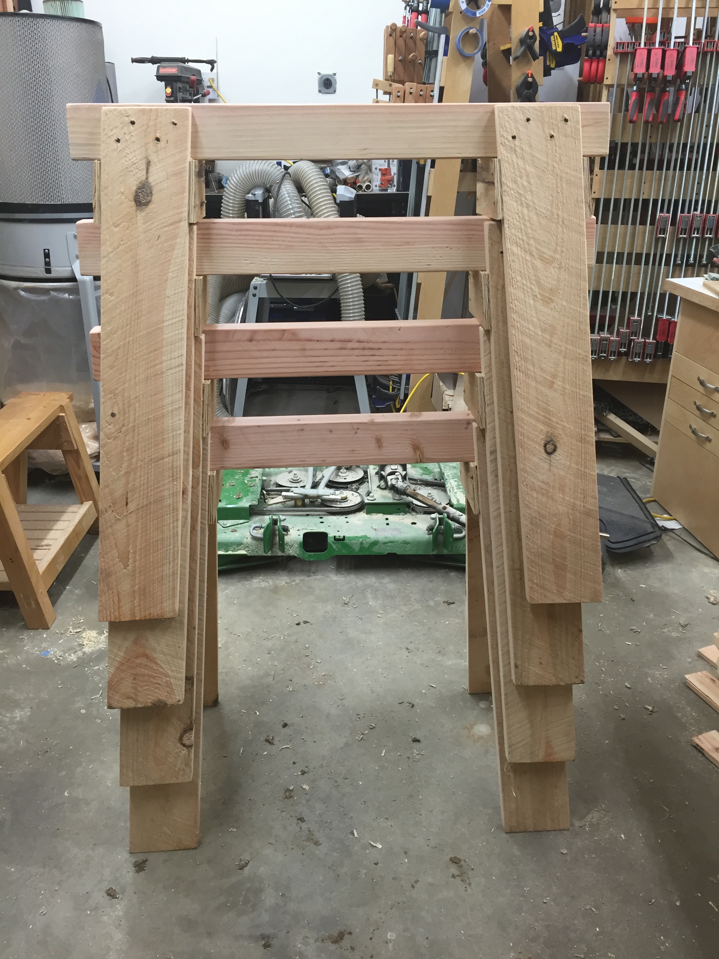
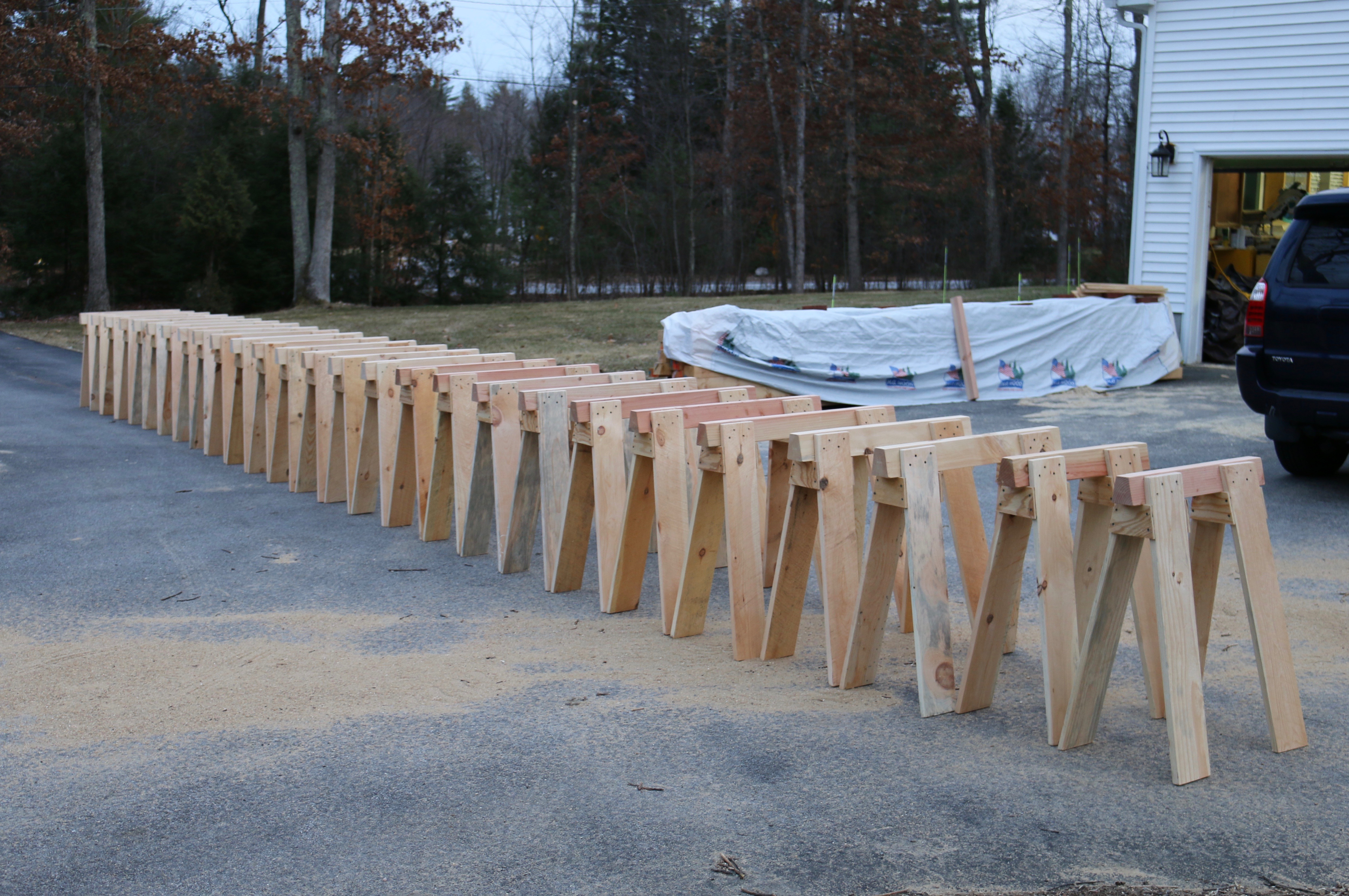
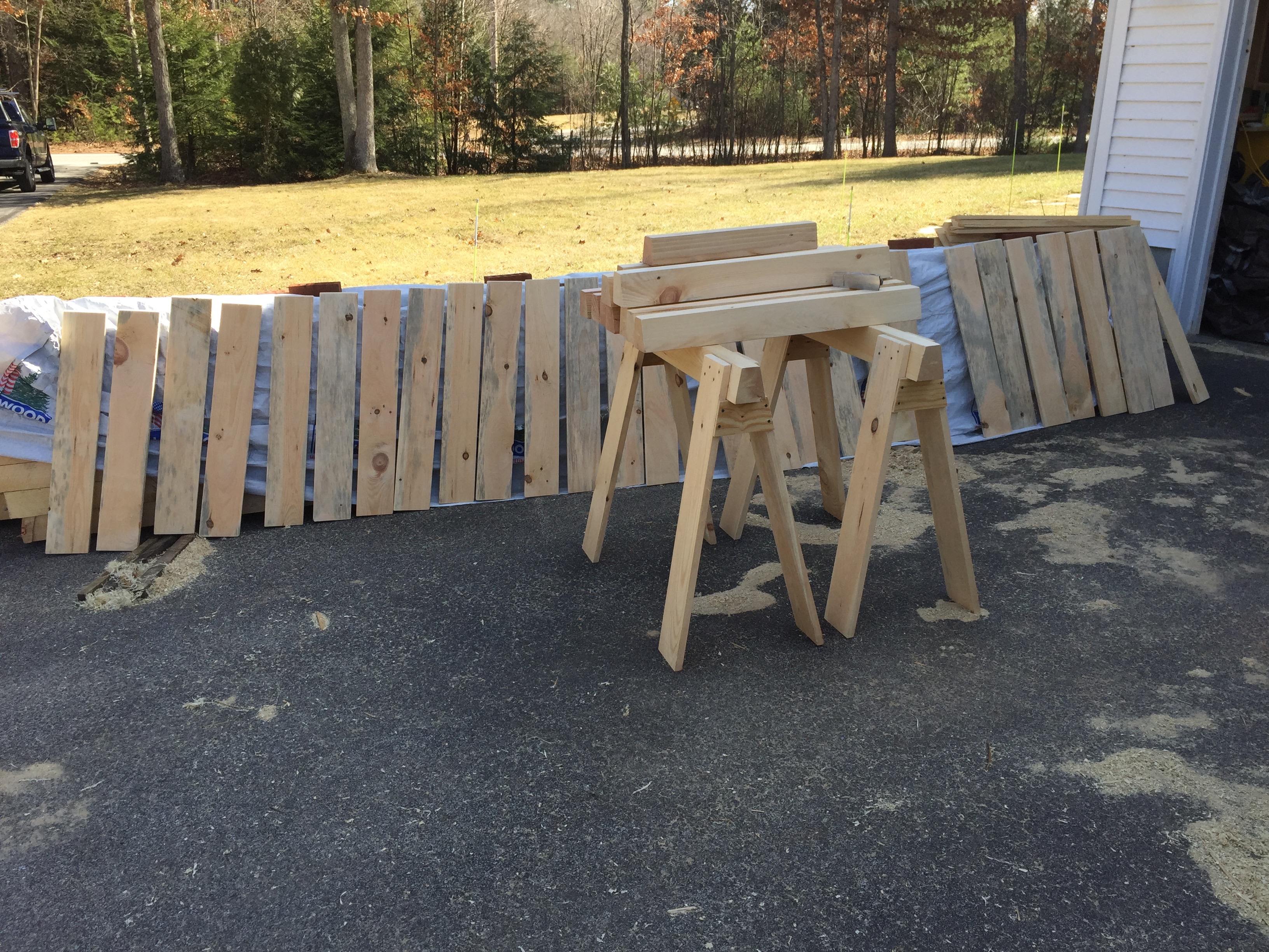
The horses stack nicely and even when stacked all the wood can dry nicely.

Wide angle view of the horses

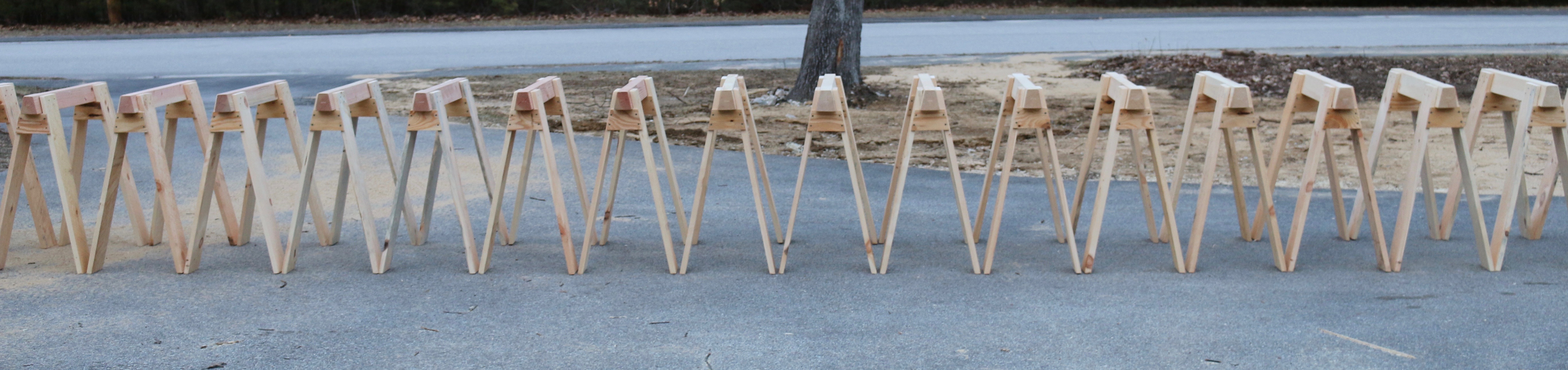
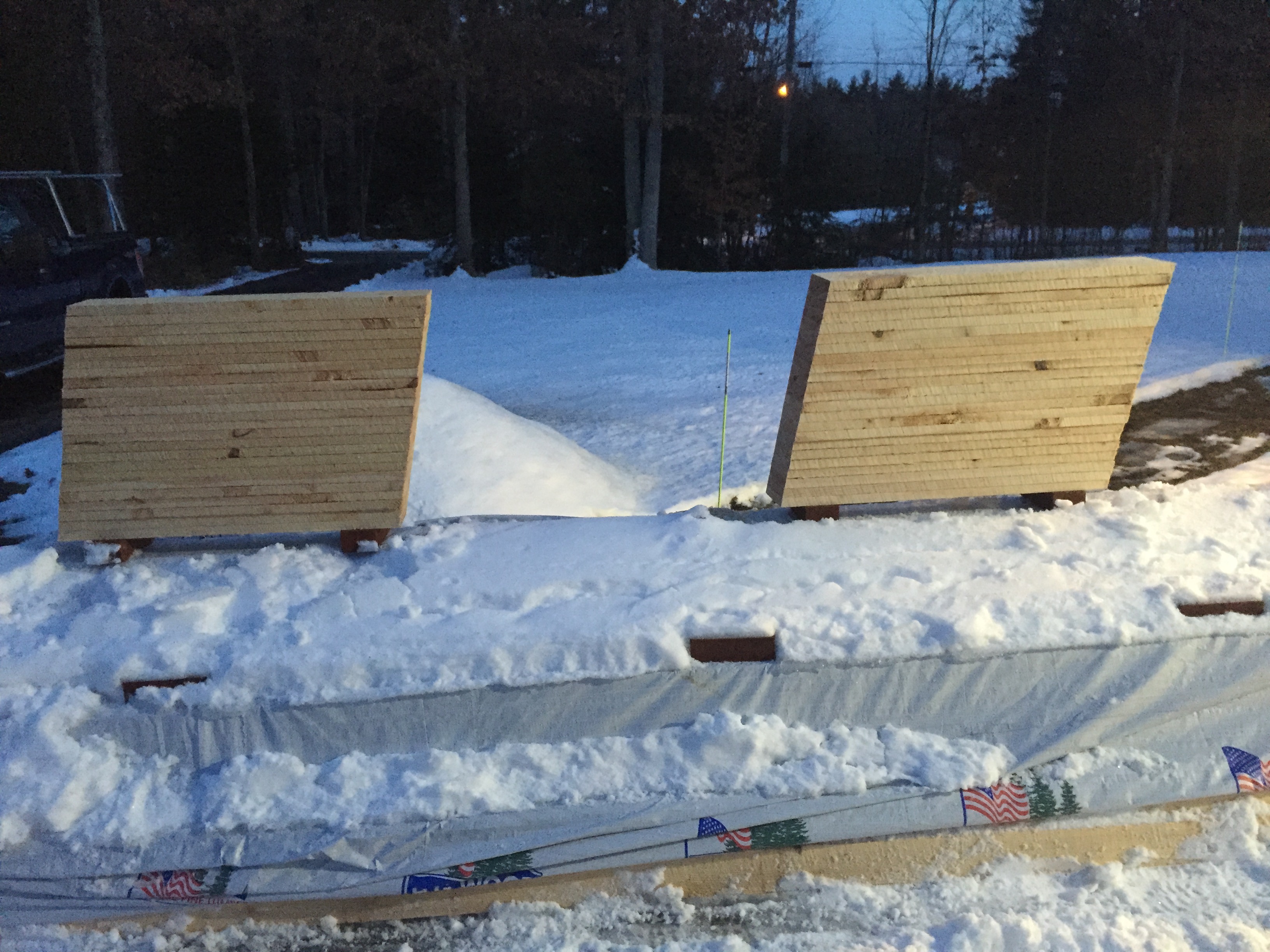
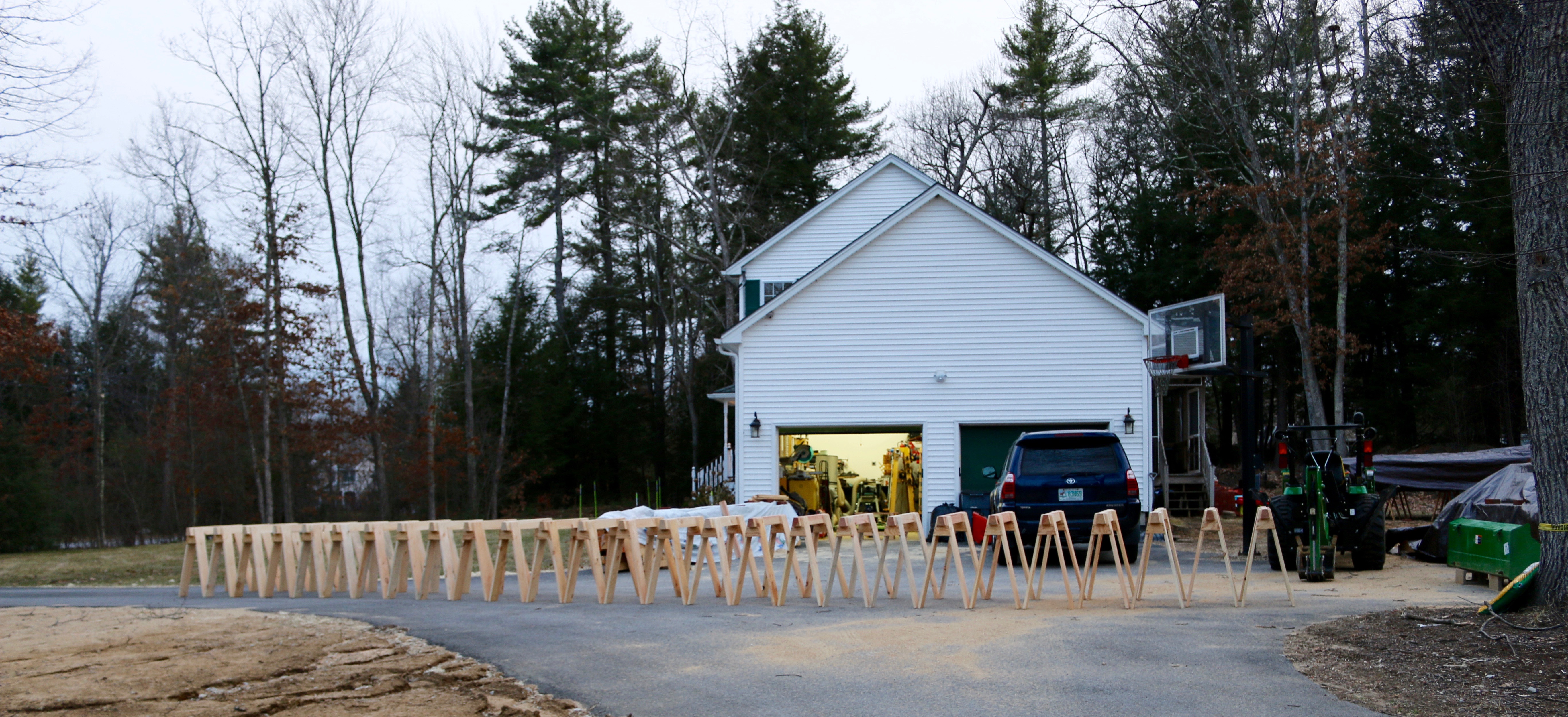
This was the largest run of horses I’ve made to date so I set them all up out in the driveway just to see them all in one place.

2 ponies in the foreground 26 horses in the background

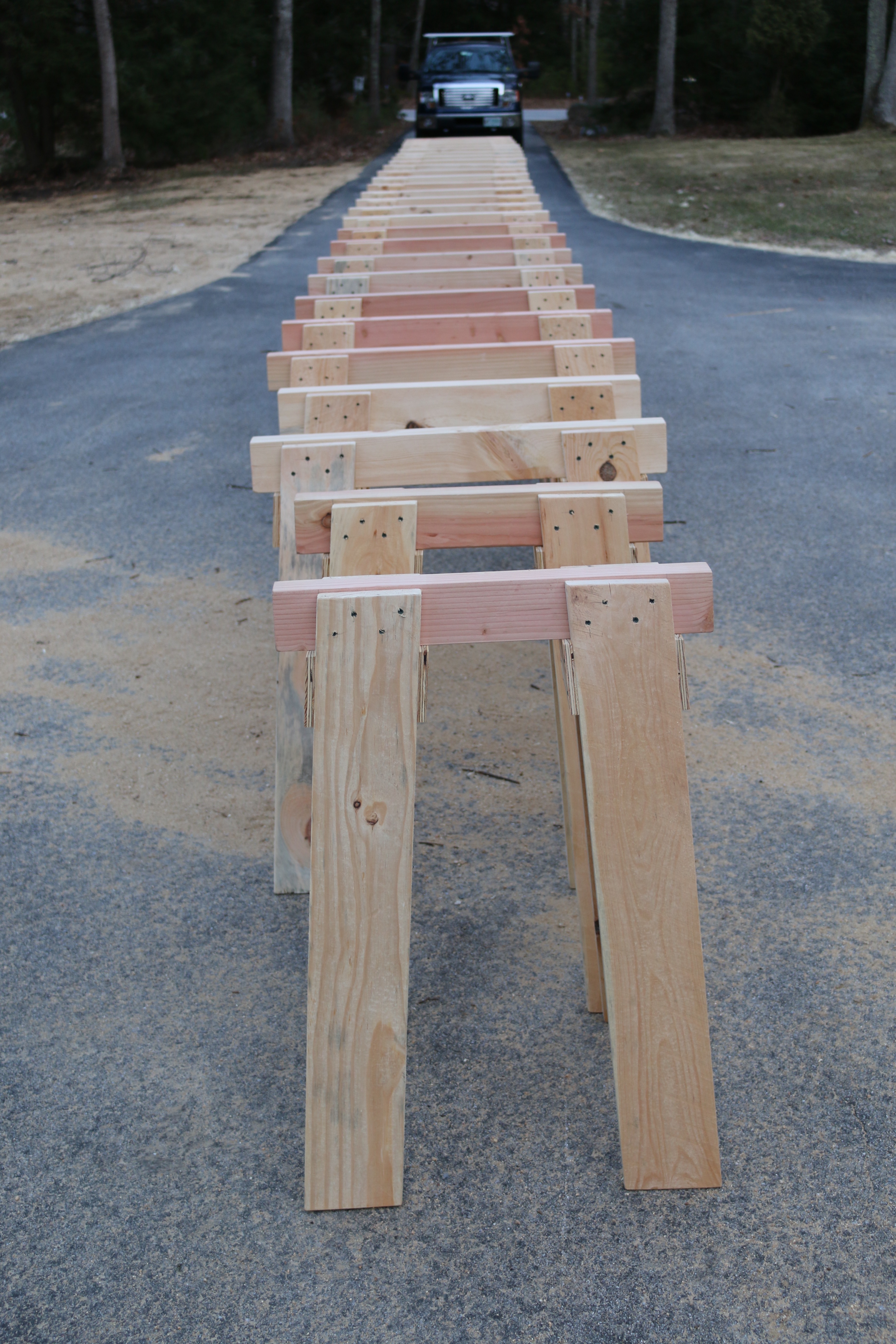
Two of the horses, my ponies,  had a 24″ beam as two of the 4x4s were a little short and I thought it would be nice to have a set that can fit into a tight place.

It looks like a TON of horses, but these 12, plus the 12 I already had will just barely be enough for the barn build.

What do you plan to do with all these horses?

A LOT of shiplap siding on horses. 10-12" wide 16' long pieces
A LOT of shiplap siding on horses. 10-12″ wide 16′ long pieces

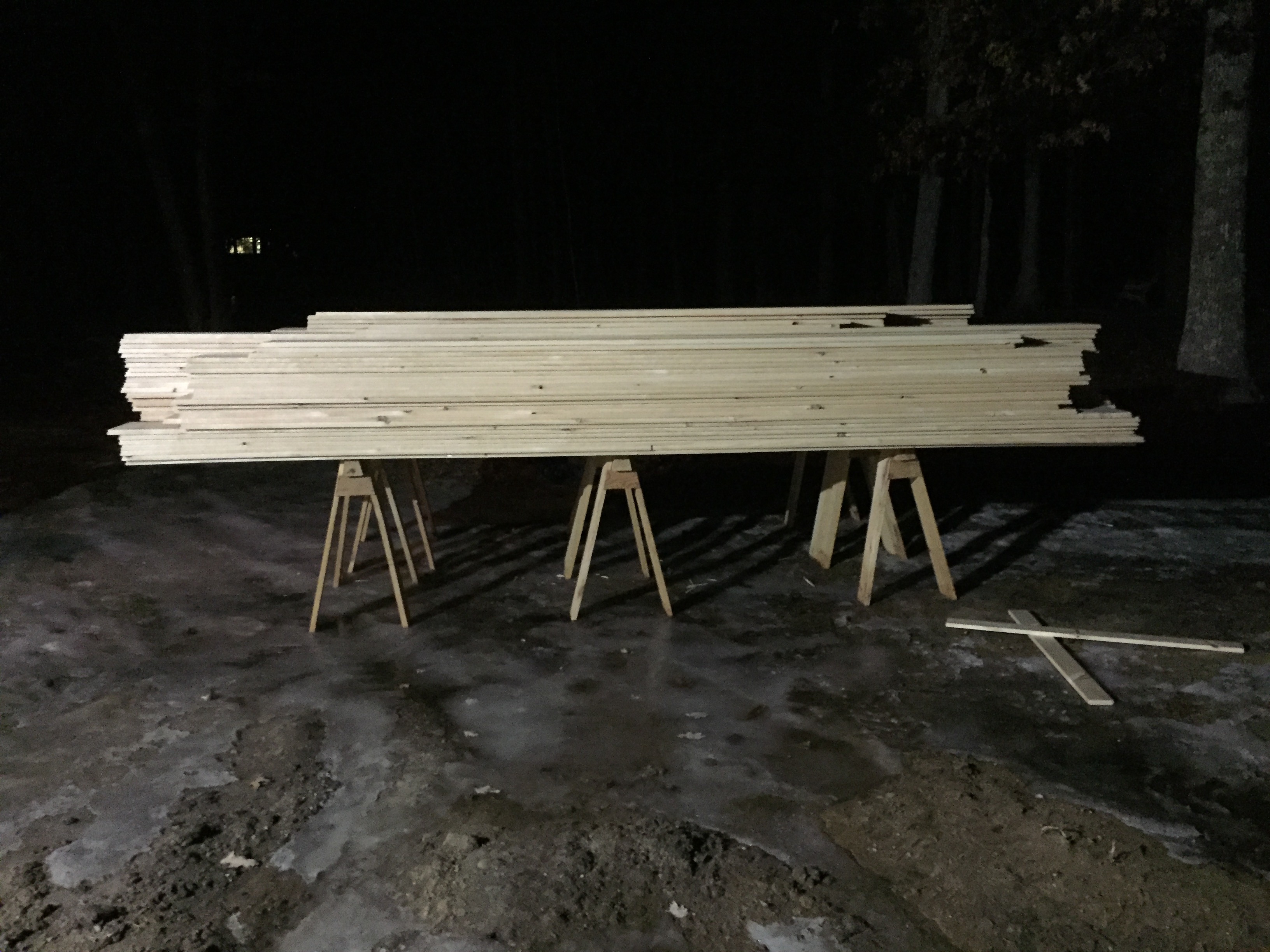
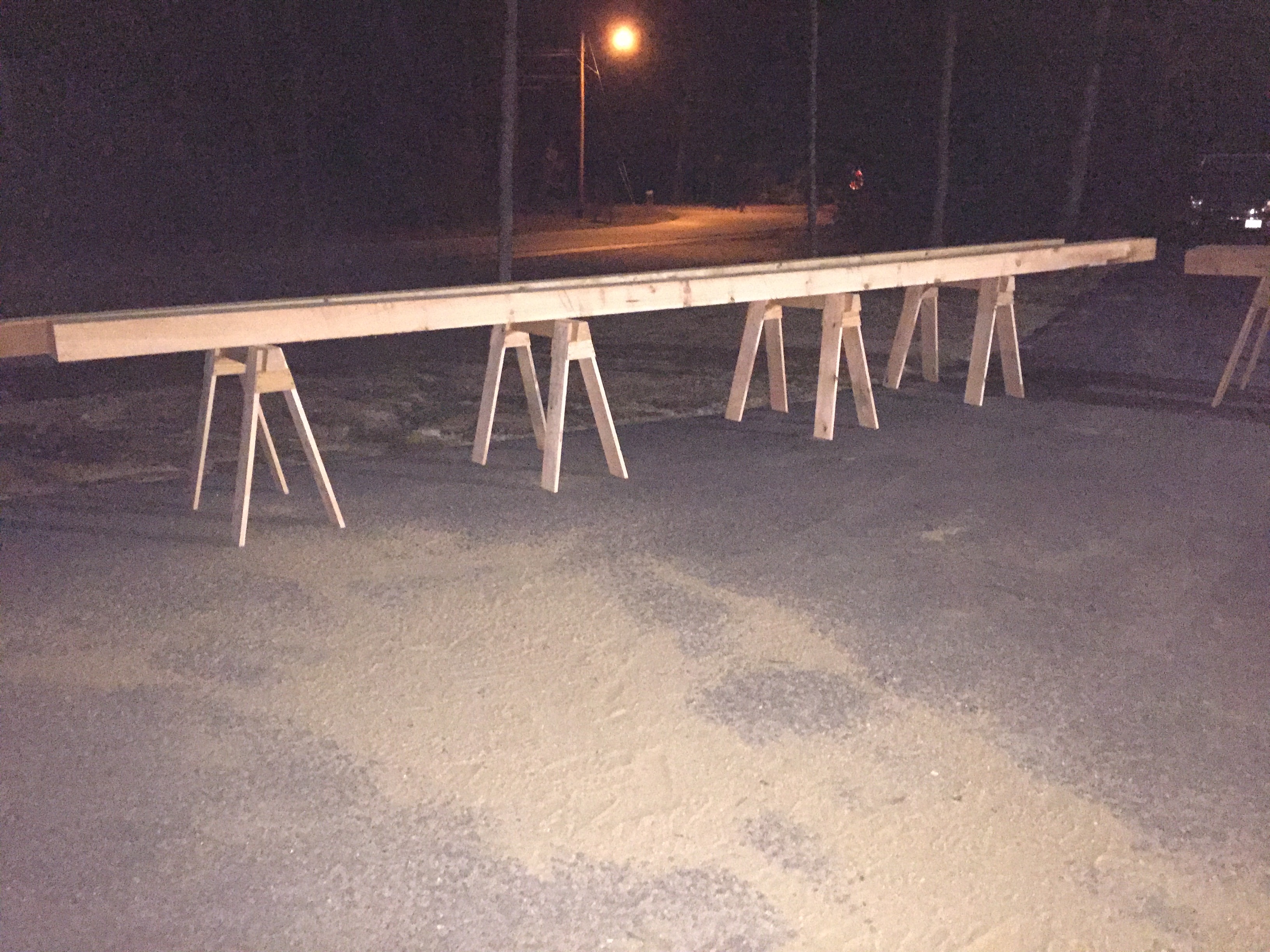
Above and below you can see a couple thousand linear feet of 16′  shiplapped pine sheathing held with ease by these horses.

A LOT of shiplap siding on horses

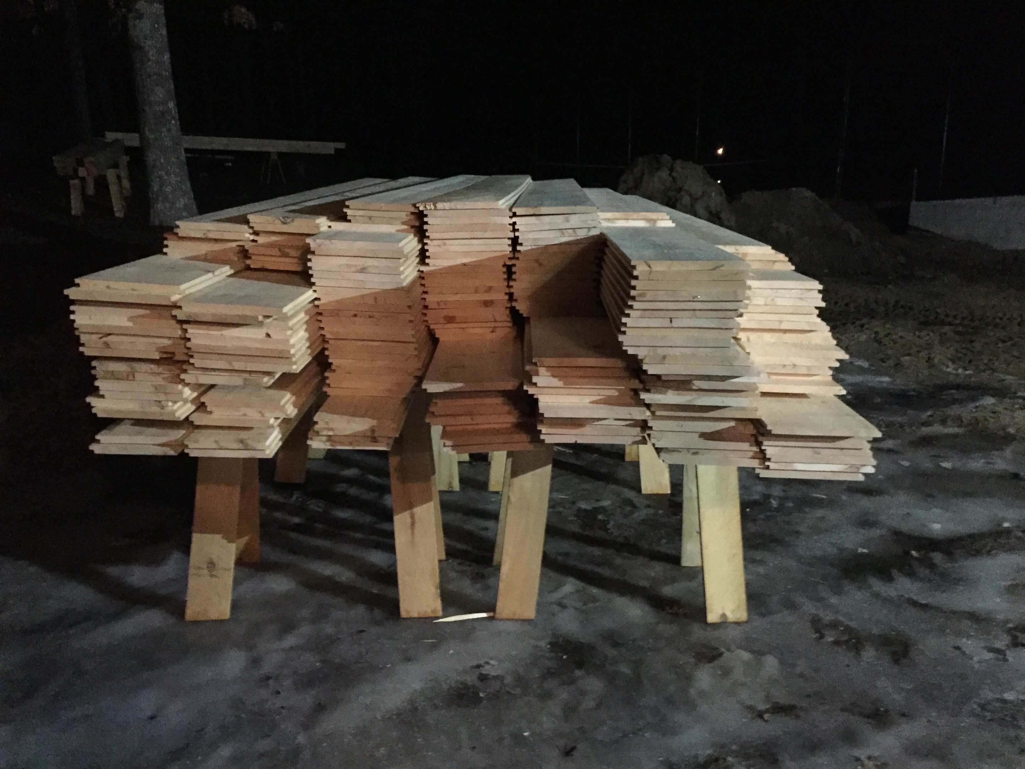
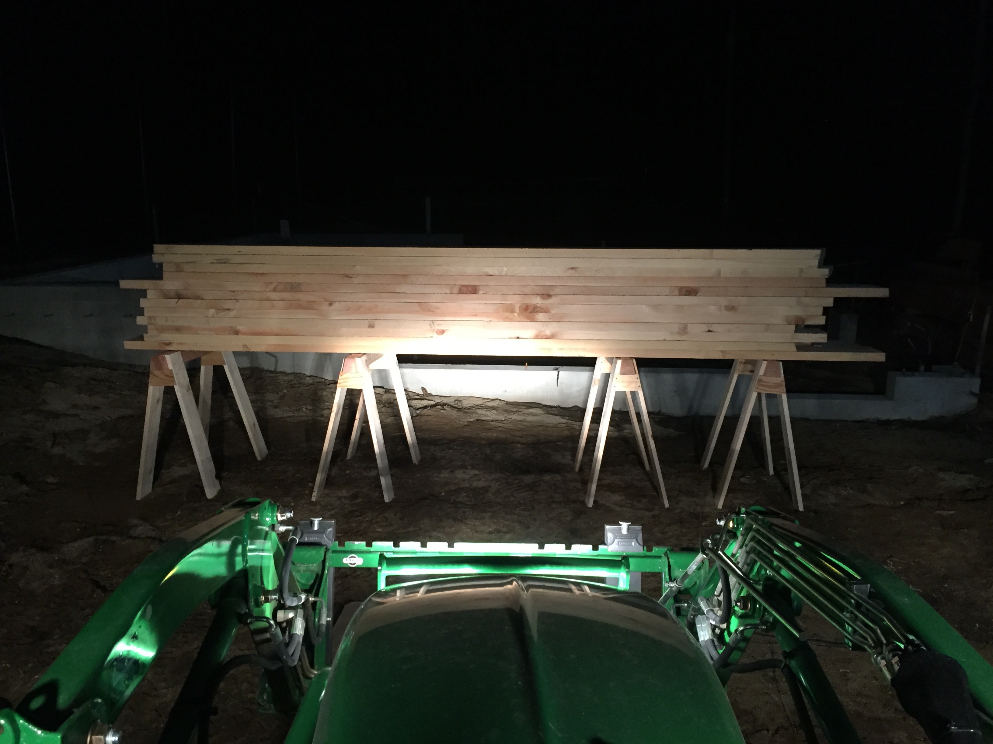
In the photo below are 24 2″ thick 12″ wide green pine planks that will be used in the barn loft. I estimated this wood to weigh 1800lbs and the 4 horses below seem to hold it with ease.

4 horses holding over 1850+lbs of green pine planking

And below are some 6×9 25′ long timbers.

Horses holding 6"x9"x25' timbers
Horses holding 6″x9″x25′ timbers

As you can see these versatile horses are at home in the shop or out on a worksite and I hope that you’ll build a few pairs for yourself. If you do, please let me know in the comments.

Take care,
-Bill

The best $1 you can spend on your workbench

I recently finished off my never-ending project — building a proper workbench. I snapped some photos figuring it will never look this pristine again. Time to press the bench into service…

Things started off great, but I wanted to set my jack plane to take a heavy cut and see how just how aggressive I could get before the bench started to move. I’m 6′-1.5″ tall and 240lbs, so if I really get going I’ve moved many a sizable bench over the years. At 7′ long and made of solid maple the bench has a good amount of mass. The problem I have is a very smooth concrete floor which provides little traction for wood.

With a concrete slab I won’t be bolting the bench to the floor so I needed an alternative. I ran through several alternatives in my head but couldn’t come up with a good solution that didn’t jack up the bench. As I sat on my sawbench looking around the shop I recalled a blog post by Chris Schwarz from earlier in the year wherein he put some sandpaper on a shim and have very good results. (You can see Chris’ post here). Sandpaper didn’t get much traction on the concrete floor, but it triggered a different thought. Years ago Rockler marketed a ‘routing mat’ which was effectively an expensive roll of rubber drawer liner. The cheap Yankee in me promptly went out and bought a roll of drawer liner for a couple of dollars and he has served me well for a decade or so now.  I went to my router station, grabbed the mat and cut out four squares roughly the size of the foot pads on my bench. I put them under the bench and repeated my experiment…

Rubber mat can help your bench stay put

To my surprise it worked great. The weight of the bench compressed the pad so much the bench height is negligibly higher off the ground. I was able to aggressively plane some hard maple scraps left over from the bench and it was solid and stationary. I’m sure someone who really wanted to move it enough could find a way, but the increase in traction was impressive. If you’re also living with a concrete floor in the shop you’ll want to give this a try — it’s about the best $1 bench upgrade you can make.

Take care,
-Bill

P.S. I’ll make some posts about building the bench, but right now I have a some competing priorities taking my much of my time. We have a baby on the way in August, I need to build a crib, and I’m teaching for much of the rest of the summer. I’ll be posting as I get some free time here and there but it may be in spurts.

P.P.S. In digging up the the blog post above from Chris I learned that I am not the first to do this sort of thing with various forms of rubber padding — nonetheless the simplicity and the results were still worth sharing.

Balloon Framing

Between Timber Framing and modern Platform Framing was an intermediate style of framing a building called ‘Balloon Framing’.

Balloon Frame 3D Model
Figure 1: Balloon Frame 3D Model

This method of framing was radical for its time. Started around the 1830s and steadily gaining in popularity through the end of the 19th century Balloon framing ushered in a new generation of building supplies and builders who benefited from and drove the advent of ever cheaper machine made nails, consistent milled lumber, and more efficient transportation methods (Rail box-cars etc). Beyond the technological advancements in the materials production and transportation this building method caught on quickly as buildings framed in this manner could be built cheaply with non-skilled labor and common nails and tools, thus farmers and do-it-yourselfers could build what they needed with a far shallower learning curve when compared to all the advanced joinery traditional timber framing required. This was invaluable to frontier areas where traditional carpenters and joiners were in short supply.

Bell's Carpentry Made Easy Plate 4
Figure 2: Bell’s Carpentry Made Easy Plate 4

In the mid-west and plains states in particular you see a lot of balloon framed houses during this period as they had good access to the mills producing these building materials, a desire to quickly build and expand existing buildings and in some areas a dearth of heavy timber needed to build in the older styles. Even in more populated areas back east you’ll see many of the Shingle Style and Victorian homes and Triple-Deckers were framed this way, though certainly some more austere farm houses of this period were also framed in this manner as it was an economical way to build. If you look carefully at some of the design details you can see how tastes and designs changed to make use of the dominant building supplies of the time. You’ll see higher ceiling heights, various bump outs, towers etc that were more easily executed with this style of framing and in keeping with the prevailing styles of the day. (See Figure 3)

Mansard Victorian in Manchester NH
Figure 3: Mansard Victorian in Manchester NH

Balloon framing made use of common sized lumber coming from mills — the first real large scale use of 2x4s, 2x8s, 1x10s etc in framing a building and marked a transition from the heavy timbered buildings of the east coast of America and the ‘Old World’ that preceded it. In the earlier part of this period a 2×4 was actually 2″x4″ in some areas as opposed to the ‘nominal’ sizes we have today wherein a 2×4 is 1.5″x3.5″ by the time it makes it to a modern lumberyard, but that is a post for another day. The weight of the building was dispersed across a series of smaller consistent studs as opposed to a few heavy posts. Also notable was the fact that the studs ran from sill to plate, thus requiring the 2nd and 3rd floors to be ‘hung’ from the studs via ledger or ‘ribbon’ boards. (See Figures 2 and 4)

Bell's Carpentry Made Easy Plate 5
Figure 4: Bell’s Carpentry Made Easy Plate 5

A great period resource for information about Balloon Framing is William Bell’s “Carpentry Made Easy: The Science and Art of Framing”. While Bell was not the first author to extol the virtues of Balloon Framing he may have been one of the most prolific. His ‘Carpentry Made Easy’ book was published continuously from 1858-1904. 46 years is quiet a testament to the information he provided. The book’s longevity is largely due to how the information is provided. Bell starts with a detailed section on basic math and geometry for carpenters and the moves into framing. He covers Balloon Framing for homes and modest sized buildings and moves on to heavy timber framing for industrial buildings, bridges, spires and the like. Bell was a trained carpenter and joiner and speaks the reader in a clear and concise way that was agreeable to most carpenters. Bell goes into technical detail but did so in such a way that any reasonably skilled carpenter could take this information and apply it to the project at hand. His words still resonate well today — in fact using his descriptions I was able to build a detailed 3D model in Sketch-Up based on his instructions for how to build a Balloon Framed structure. (See Figures 1 and 5). I’m sure that many a house carpenter had a dog-eared copy of this book in their toolbox and regularly referred to it over the years.

How fast did this transition happen?

Like most major shifts in an industry the transition from Heavy Timber Framing to Balloon Framing did not happen over night. The word had to get out, it had to be evaluated, the supplies had to be ready and a host of macro-economic pressures had to come together in order to facilitate this change — a strong need to build economical housing for an exploding population etc. Like most things, some isolated or rural areas clung to the old ways for longer periods and some areas were more willing to try out these new techniques. Even cutting over in terms of technique was an evolutionary change. If you look closely at Figure 4 above you’ll see that the house shown there has Balloon Framed walls with a heavy timbered sill, which the author notes as the preferred way to go if heavy timber is available, as opposed to Figure 2 which shows a more traditional balloon framed sill made from 2x framing elements.

In broad terms this building method started in the 1830s, crescendo-ed during the 1880s-1930s giving way to modern Platform Framing which was an evolutionary advancement that built upon the strengths and lessons of this movement. Balloon Framing and it’s relative efficiencies greatly improved the living conditions of many Americans and others of modest means and the burgeoning middle class.

Balloon Frame Cutaway 3D Model
Figure 5: Balloon Frame Cutaway 3D Model To Show Joinery

Why did Balloon Framing disappear? Disadvantages and Demise

With Balloon Framing, you framed an entire wall at once from sill to top plate, thus requiring longer framing members. Once the wall was standing you needed to have ladders and scaffolding in order to ‘hang’ the upper floors from the ledger plates and studs. This required more labor compared to modern platform framing where each level builds upon the lower level, thus requiring less labor, scaffolding and smaller framing members.

In some larger Balloon Framed buildings you’d see some sagging towards central walls due to differential shrinking of the framing members — joists resting on ledger boards will move a different amount when compared to joists nailed into the side of as stud. This kind of differential can add up in a larger building and took time to manifest itself. (See Wikipedia here for a more detailed explanation)

While the above items are negatives for this system of framing the final nail in it’s coffin was how it performs in a fire. The inter-stud wall cavities that run from sill to plate worked like a chimney flue and helped to rapidly spread fire throughout a Balloon Framed building. To counter this, fire blocking can be installed between each floor, but this was labor consuming to install and not quite as good as the fire resistance you’ll see in a Platform Framed building. Even today when filling out an application for homeowners insurance you’ll often see questions related to this kind of framing.

What replaced Balloon Framing?

Around the 1930s the death toll and property loss data was starting to add up and folks looked to rectify the situation. The solution was Platform Framing. In a nutshell you’d build a platform of sill, joists, rim joists and sub-flooring, use this as a platform to build the walls for one floor, you’d tilt up and nail off the walls, then build another platform on top of that until you top out your building. This method required less labor, shorter framing members and by breaking up the wall cavities at each floor provided better fire resistance.  After World War II the post war building boom accelerated the need for even more housing and faster build completion times. At this time we started to see the introduction of studs 16″ to accommodate sheet goods (Plywood and later OSB) in regular sizes as a replacement for more labor and material intensive traditional sheathing. And in a similar manner vinyl siting replaced genuine clapboards etc etc until you get to present day building materials and practices.

Conclusion

We don’t often see or hear much about Balloon Framing today as it has fallen out of favor in the building community, but it’s impact can be felt today in any Platform Framed structure that benefited from all the lessons learned by this earlier incarnation of efficient home building. I hope that the next time you are examining the framing of a Balloon Framed structure you’ll take a look and see what lessons it can teach you.

Take care,
-Bill

P.S. If you’d like to read William Bell’s “Carpentry Made Easy: The Science and Art of Framing” (1858) you can get a copy from the Toolemera Press here. It was a great read with interesting sections on timber framing, compound roof joinery, bridge-building, spire making and other interesting building topics above and beyond the Balloon Framing and carpenter’s geometry I mention in this article.

** Plates 4 and 5 of from Bell’s Book are provided via Gary Roberts of the Toolemera Press and used with his permission.

Lights, Camera, Action….

I’m happy to report that the companion video series for my recent Fine Homebuilding article ‘Master Carpenter: Reproducing Traditional Moldings’ went online today.

Behind the scenes. (Photo courtesy of the Taunton Press)

I had a great time making the videos and I hope you will enjoy watching them. Several of them are free, though a few of them are reserved for FineHomebuilding.com (FHB) members only.

Bill Rainford using molding planes to reproduce traditional molding profiles. (Photo courtesy of the Taunton Press)

Details below as they were presented this morning in Fine Homebuilding’s e-newsletter and where to find the videos:

Fine Homebuilding Logo

In this Master Carpenter series, Bill Rainford shows how to get period details right with both power and hand tools.

Watch the intro video

Plus watch more free episodes from this series:
Interview with the craftsman
Bill chats about how traditional carpentry is better for his body and soul
An inside look at old-fashioned home building
Bill and senior editor Chuck Bickford visit the Alvah Kittredge House and dig into its traditional construction details

Sign in as a member or sign up for a FREE 14-day trial to see this complete series and much more.

Take care,
-Bill

Let There Be Light — Installing New Hand Built Windows

In many posts we’ve talked about why old windows are worth saving and how to build or restore  sash for them, but not much on what it would take to build a new window complete with jamb and trim and install it.

Completed window installed in the side of the barn

A while back I had just such an opportunity when working on the timber framed barn workshop of my friend Rich. Much of the work for these windows took place in the shop — building traditional single hung (one moving sash) true divided light windows. A hand built window can offer a VERY long service life, be easily repaired and often look much better than anything you can buy commercially. The ability to build a new jamb to go along with your sashes will allow you to really fine tune the movement of the windows, the exact choice of hardware — if any and allow you to create a distinctive look for your home.

Bill cutting through the wall to install my window.

Once the shop work was completed, the jamb is complete, the sash are fitted, glazed and the paint has dried it was time to install the completed window unit into the barn.  When working on a timber framed barn you’ll want to make sure you’ve carefully laid out where you want the windows to go — you generally do not want your window obstructed by braces or other framing members. You’ll also want to make sure that you have added in sufficient nailers and/or studs so that your window can be firmly attached to the building.

These hand built windows, complete with jamb, sills, casing and leaded flashing install much the same way you would install an Anderson or Pella new construction drop in window. You’ll want to take the same time and effort to level the window, add insulation if needed, and flash out the window. Once installed you can trim out the interior of the window to blend with the interior surfaces.

Me posing with the newly installed window

If you’ve invested the time to learn how to build a traditional window sash, building an entire window as described here can be a very enjoyable and rewarding experience — plus with these new found skills you can go off and build a window of any size and shape.

Below is a quick slideshow of the above windows being installed into a timber framed barn.

This slideshow requires JavaScript.

A Staircase for Very Skinny People

As a student at the North Bennet Street School, one of the many projects Preservation Carpentry students have to complete is the staircase model. The project is a great exercise for students as they each get to walk through the process of building a staircase from end to end. The only caveat is that the stair treads are only about 18″ wide since going full size in width does not add much to the learning experience and makes it feasible to have 10+ staircases in a single classroom.

Rough stringers in place

Above we start off laying out and cutting the rough stringers and then move through each stage until we have a completed staircase. This is one of the projects wherein the students have some design freedom in how they want to trim out the staircase. Some were very modern and minimalist, some very plain vanilla with all square stock, some very traditional.

Turned walnut ballusters
Turned walnut balusters

I am an avid turner and had done a lot of finish carpentry before coming to the school so as a challenge to myself I decided I wanted to turn my own newel posts and balusters and finish off the piece as if it was installed in a house. It was a lot of extra effort, but a great experience. Once completed my staircase model was on display as part of the NBSS annual student works show and exhibit.

You can see the completed project here:

Completed staircase model

If you are interested in seeing a time lapse of how this staircase was built, please check out the slide show below:

This slideshow requires JavaScript.

The View From Up Here — Custom Loft

Another project from back in 2005/2006.

This loft was a great project with a lot of interesting challenges. This townhouse had a 2 story vaulted ceiling above the living room, dining room and kitchen and was designed in such a way that a loft would fit nicely above the dining room dividing wall.  By installing the loft with a lot of natural cherry trim it really warmed up the space, gave the dining room a much better sense of scale and sophistication and added ~150 square feet to a modest size townhouse.

The Before:

Loft Before
Loft Before

The After:

Railings, hand rails and ladder completed and installed. Matching cabinet is for storage of the ladder when not in use.

Highlights:

  • I designed and built this project from end to end
  • Solid cherry railings with hand and floating toe rail
  • Solid cherry custom access ladder
  • Can lights including detailed alcove for displaying art or similar highlights
  • Antiqued Maple flooring
  • Storage compartment to store ladder out of the way when not in use
  • Stainless steel hardware, grab bars, and matching cherry ladder storage compartment to match with existing kitche

Challenges:

  • Blending knock texture between new and old work
  • Building a 9′ custom ladder
  • Working in a tight space and protecting the rest of the townhouse

This slideshow requires JavaScript.

Mission Accomplished — Custom Mantel

Jumping back to an oldie but a goodie from ~2006.

The Challenge — dress up a plain Jane fireplace insert in a new townhouse.

The Before — just the tiled hearth box, the insert surrounded by textured Sheetrock and a pre-made shelf that was serving as ‘mantel’

The After — tiled surround and crisp clean lines of a mission style mantel

Detail view of corner

The final result:

WIde angle view of mantel
Wide angle view of mantel

Details:

  • I custom designed, drafted, built and installed this piece
  • Tracked down and installed matching tiles from the builder to tile a surround that matched the hearth box
  • Frame and panel construction
  • Built up complex molding
  • Primed and painted finish

This slideshow requires JavaScript.

Classic Stick Framed Shed

Back in the spring of 2010 I had the opportunity to design and build a very traditional stick framed shed. This project served as a great lesson on modern stick frame/platform framing construction techniques. In addition to top quality materials the project also had an emphasis on how traditional designs can be executed in a modern context while also maintaining high levels of craftsmanship.

View from the front of the barn. PT Access ramp installed.

Details:

  • 12′ x 16′ Stick Framed Shed
  • Cedar shingled exterior
  • Hand built doors
  • Period Hardware
  • Transom Window
  • Corner boards and detailed trim

This slideshow requires JavaScript.