Back in early October of 2016 Festool offered a special edition of their new Sander for an amazing $99 which also included a $50 off coupon towards another tool. It seemed too good to be true given how expensive all my other Festools are. Within hours of the announcement I placed my order. I would think I must have been one of their earliest orders. A couple days later there were notes that the demand was so overwhelming that Festool told its network of dealers to stop taking orders. Then the waiting started….and dates kept getting pushed out.
I waited and waited and waited and in very late March of 2017 I *finally* received my new sander — 6 months is a LONG wait. I’m not sure what Festool’s reasoning was for the special package — some said it was supposed to be a thank you to loyal Festool customers, others said it was a good way to get folks hooked on their tools. Either way the demand was overwhelming I am glad that they eventually honored the order.
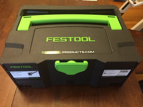
Here’s what came in the special color Systainer 2:
Contents of the Festool PRO5 LTD KitI was happy to see that Festool included some extras in there — an adapter for non Festool vacuums and a sampler pack of their Granat Abrasives (Which I think was added by the tool dealer ToolNut.com) rather than the 1 piece of sandpaper that would otherwise come with the unit.
Festool PRO5 LTD Special Color Systainer 2The Systainer 2 is a nice dark Festool blue and has space for some optional accessories and some limited abrasive storage.
Left Porter Cable Random Orbit Saner, Right Festool Pro5 LTD Sander.The new sander is lighter and better balanced than my trusty old Porter Cable 5″ Random Orbit Sander that I’ve had over 10 years now. The power switch is nice and big and the 13′ cord is nice. When paired with my Festool CT36 Dust Extractor the dust collection with the PRO 5 LTD is exceptionally good. Also the pad break is neat as the unit stops spinning fast. I normally use my trusty old ‘sander sitter‘ as a safe place to let a sander spin down and clean off an abrasive pad that has loaded up. The suction is so strong that the PRO 5 LTD will lift the rubber pad right out of the sitter — something I never saw with any of my other sanders (5″ or 6″ ROS with same CT36 attached)
The machine is well balanced with a tight stroke, powerful motor (Which I believe is brushless) and has noticeably less vibration compared to other sanders I’ve had over the years. The ergonomic handle is nice and rubberized texture provides good grip. Sometimes with 2 hands on the unit I find my second hand wants to cover the motor exhaust port a bit but the heat will quickly remind you to move that hand.
Left Porter Cable Random Orbit Saner, Right Festool Pro5 Sander. (Note the differences in dust collection holes)Too good to be true?
Like most things that seem too good to be true there is usually a catch. If you look at the image above you’ll see this Festool Sander and Festool abrasives have a VERY different pattern for dust extraction holes. That means you are locked into their abrasives. I haven’t seen any 3rd party companies sell pads with the same pattern yet. Like most things Festool they are expensive, but also very good quality. The abrasives have been long lasting and consistent and slow to load up. I
already have a few hundred dollars invested in Mirka Gold 5″ and 6″ and Abranet abrasives (which I keep in old style Systainers with 4 latches designed to hold sanding pads. I got those Systainers on clearance when the new style Systainer came out a couple of years ago). I don’t look forward to having to buy and stock another assortment of Abrasives but probably will as I am otherwise very happy with this new sander. I wish the advertising was a bit more straightforward in noting the above hole difference.
I hope that Festool, or a 3rd party compatible manufacturer will make a replacement sanding pad that also has the old style dust extraction hole pattern.
The Verdict
If you can look beyond the sanding pad hole location issue it is otherwise a great random orbit sander and I am very happy with it. I wish I ordered more than one unit.
An early lesson in carpentry or woodworking in general is to take all of your measurements from a single reference face — this way you don’t get a bunch of accumulated errors that will throw everything off. It makes sense, but what do you do when measuring long distances? or uneven surfaces?
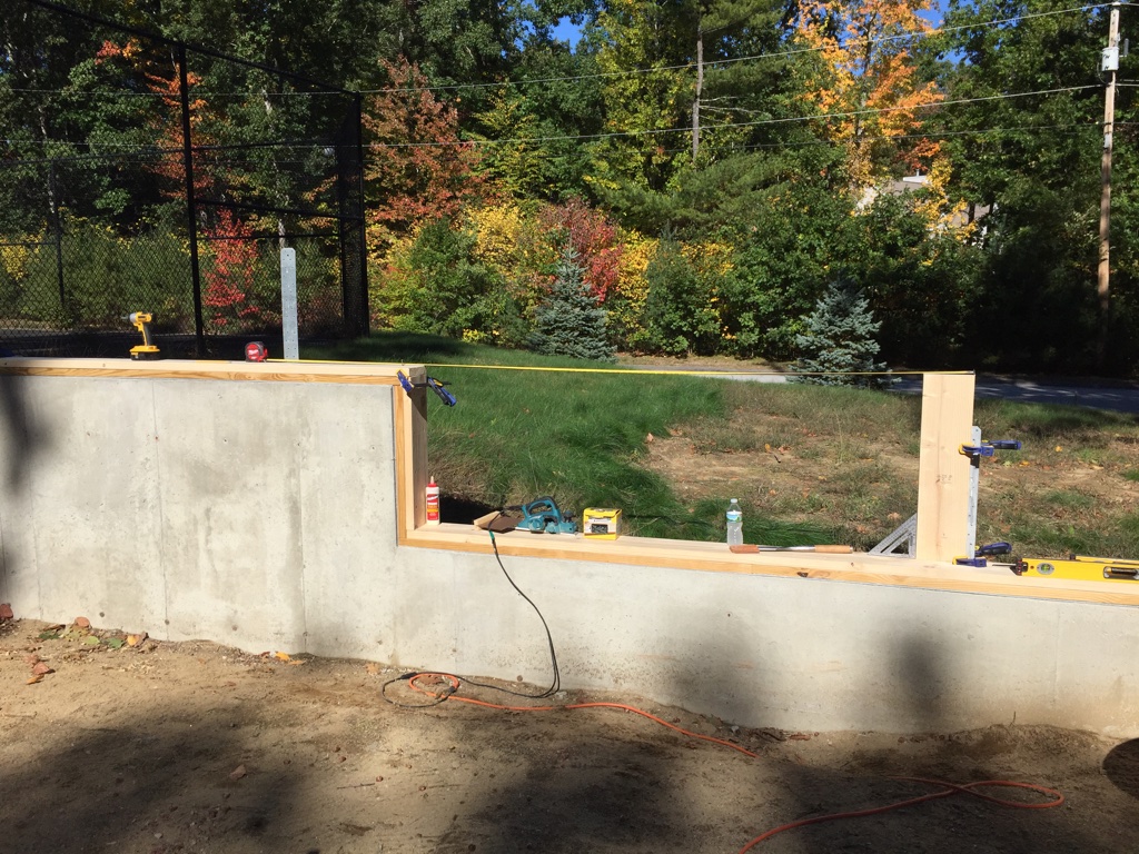
Let’s take a look at this 30 foot long foundation wall I am working on:
A view of the tiered foundation
In order to lay out the mortises in the sills for the posts I needed to make sure they are in the correct location which was a bit of a challenge.
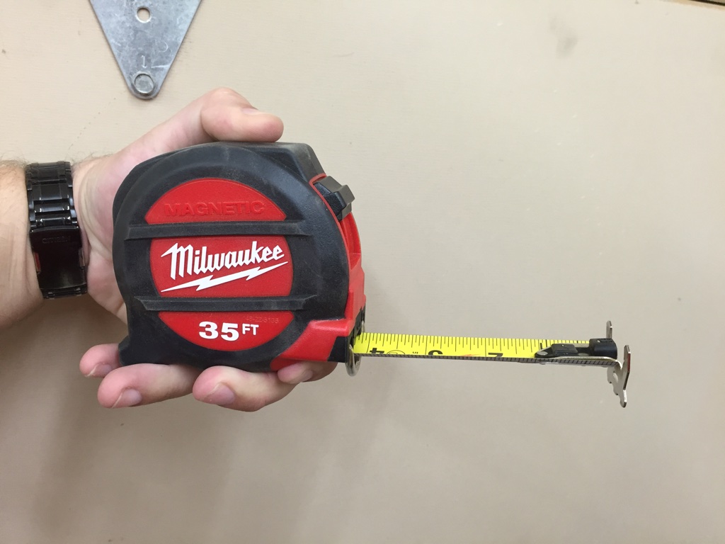
First off I had to go out and get a 35′ long tape measure. I bought a Milwaukee 35′ Magnetic Tape Measure from Home Depot.
35 Foot Milwaukee Magnetic Tape Measure
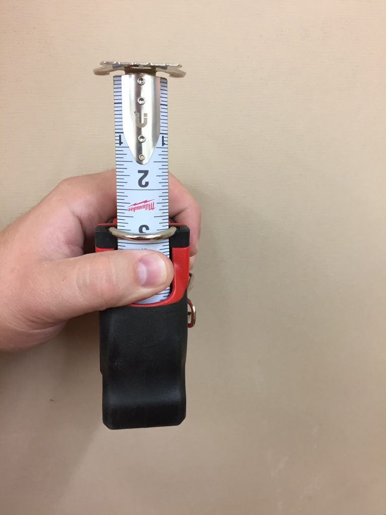
Beyond the length this model has a few nice features I really liked. First and foremost it has a finger protecting stop which is great for people like me that tend to use a thumb as the brake and occasionally get pinched by the end of the tape slamming back into the case. It also has an 8-9′ standoff (distance tape can hold itself out before it bends), a magnet in the end, large hooks and an architect scale (total inches rather than feet) on the bottom of the tape and a supposedly limited lifetime warranty.
Love that metal finger protector
I liked it so much I hope to get the 25′ model soon and will retire my Stanley and Stanley Bostitch tapes. You can find the 35′ model here. It’s a bit of a beast, so for everyday use I think the 25′ model will fit better in my tool belt.
In measuring the foundation I found out that its about 1/2″ shy of 30 feet. Other than that I’ve been very happy with how the foundation came out and across its width its consistently 24′ wide as expected.
Laying out the first two sets of mortises from the front of the building was easy and straight forward. The 3rd set is where it got tough as I’d have to bridge the vertical step in the foundation. In order to make that jump I cut a piece of scrap 2×8 and using a level and a square set it exactly on top of the center line for the 2nd set of mortises and clamped it firmly to the cast in place straps.
Measuring and compensating for the different levels of the foundation
I could then pull the tape and lay out where that third set of mortises should be and also measure to the end of the building to confirm it matched what I got when just measuring the side of the foundation in a single pull. All the measurements lined up with what I expected, so that was good.
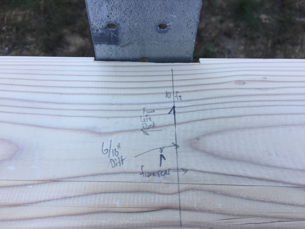
Figuring our the difference between measuring off the common reference face vs from each end of the foundation
It looks like when the straps were cast in place the concrete contractor measured from the back wall of the building rather than a single reference face and I could see the 1/2″ off they were due to the overall length of the building being off. Thankfully the posts are sufficiently large (6×6) that this won’t be a visible issue.
This all goes to show the value of taking your time and measuring as described above, for if I didn’t do this and laid out the top plates as if the building was an even 30′ long and if I laid out that 3rd set of posts 10′ off the back wall there would be some major problems during the barn raising.
Transitional planes are the pariahs of the woodworking world. The tool collectors don’t want them. Patrick Leach burns them in a funeral pyre. I’ve had a few over the years I got for a song and kept in the shop mostly for decoration.
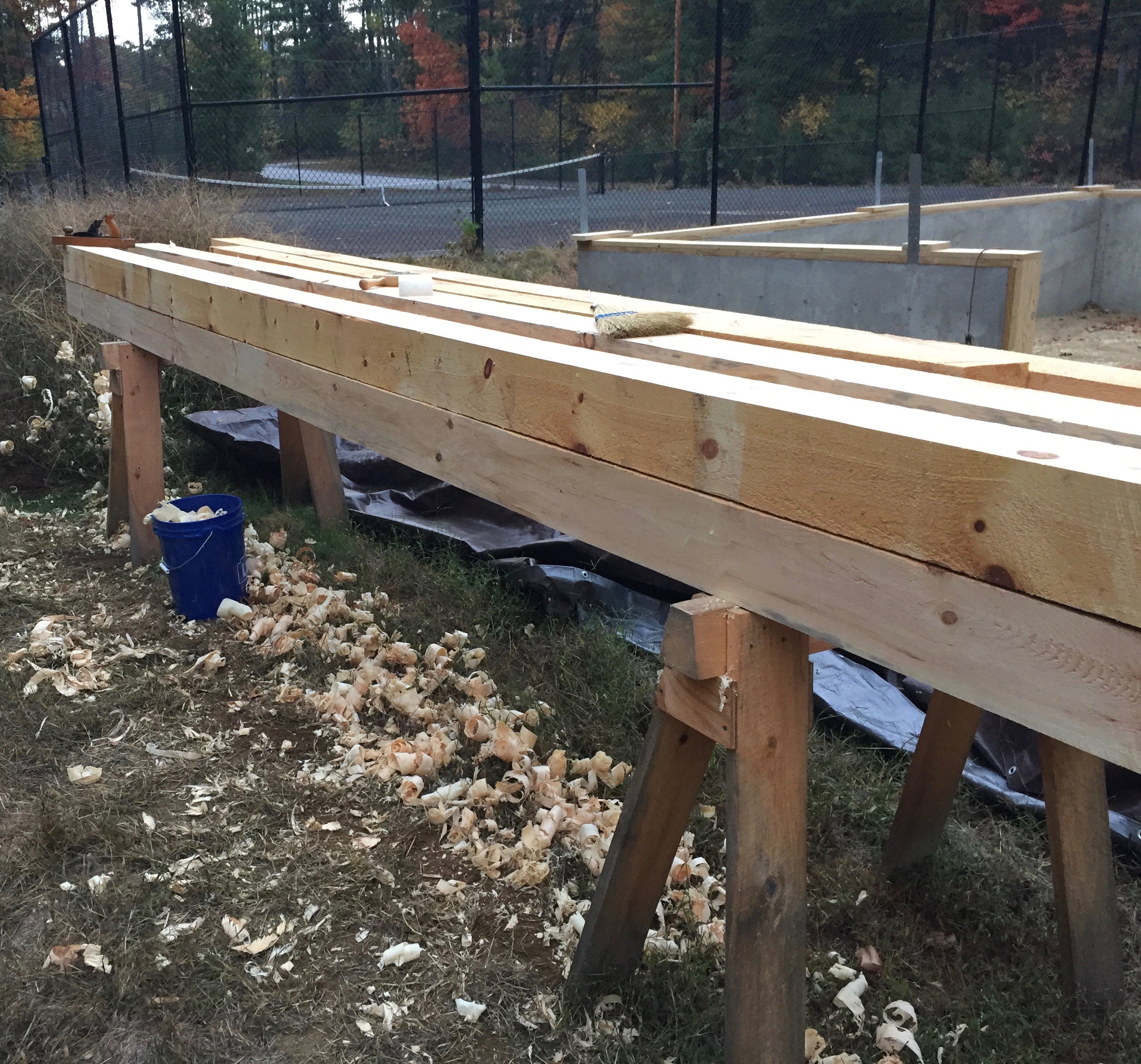
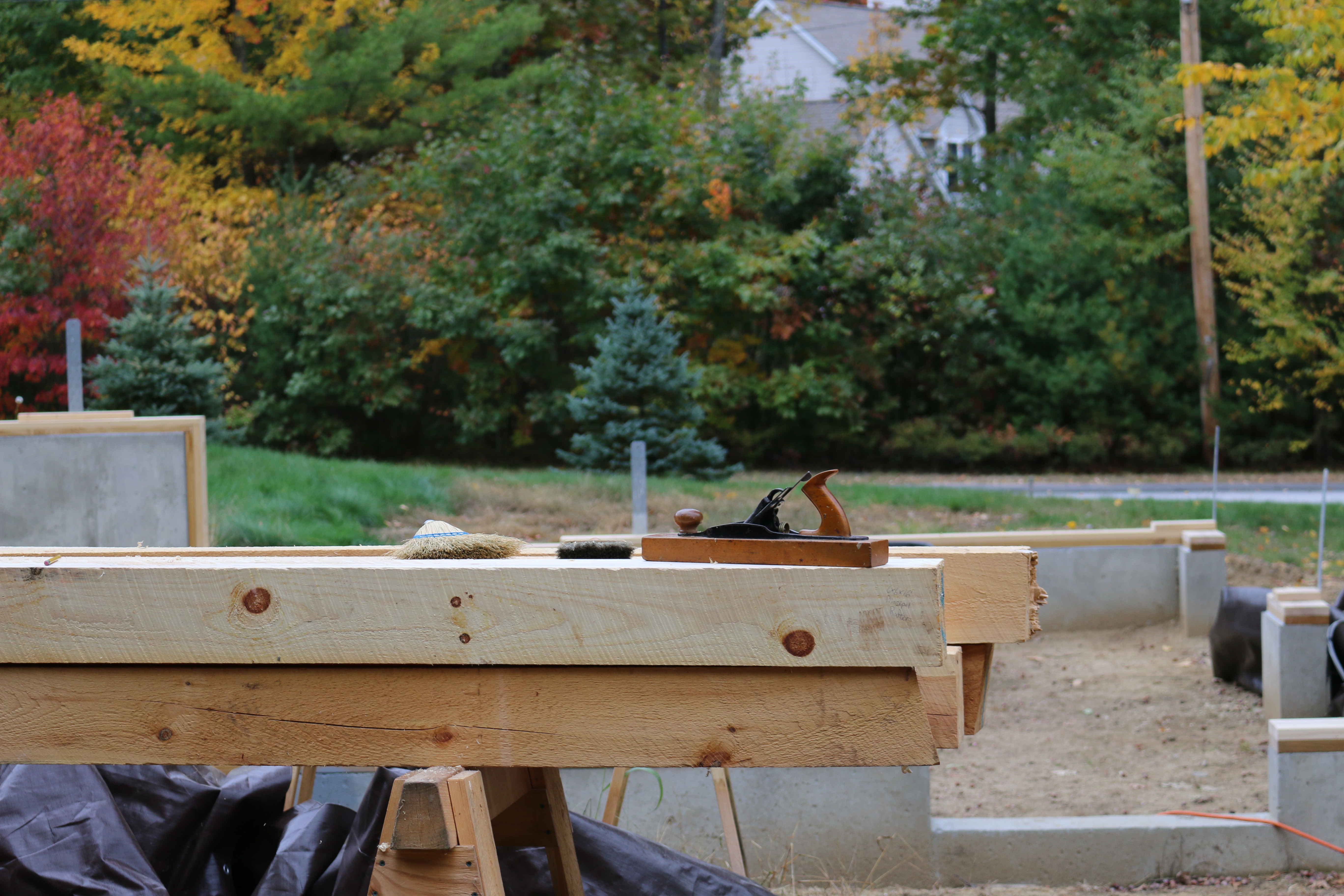
Cleaned up timber frame post
As I got more into timber framing and working with green timbers it dawned on me that these transitional planes — at least in the jack and jointer sizes might be useful for cleaning up timbers. The large wooden sole doesn’t rust the way a metal plane would when exposed to wet wood for long periods of time and you have a more or less modern Bailey style mechanism. The one annoying thing about the mechanism on a transitional plane is the blade advancement wheel spins the opposite way a metal plane works, but after a few minutes you get used to it.
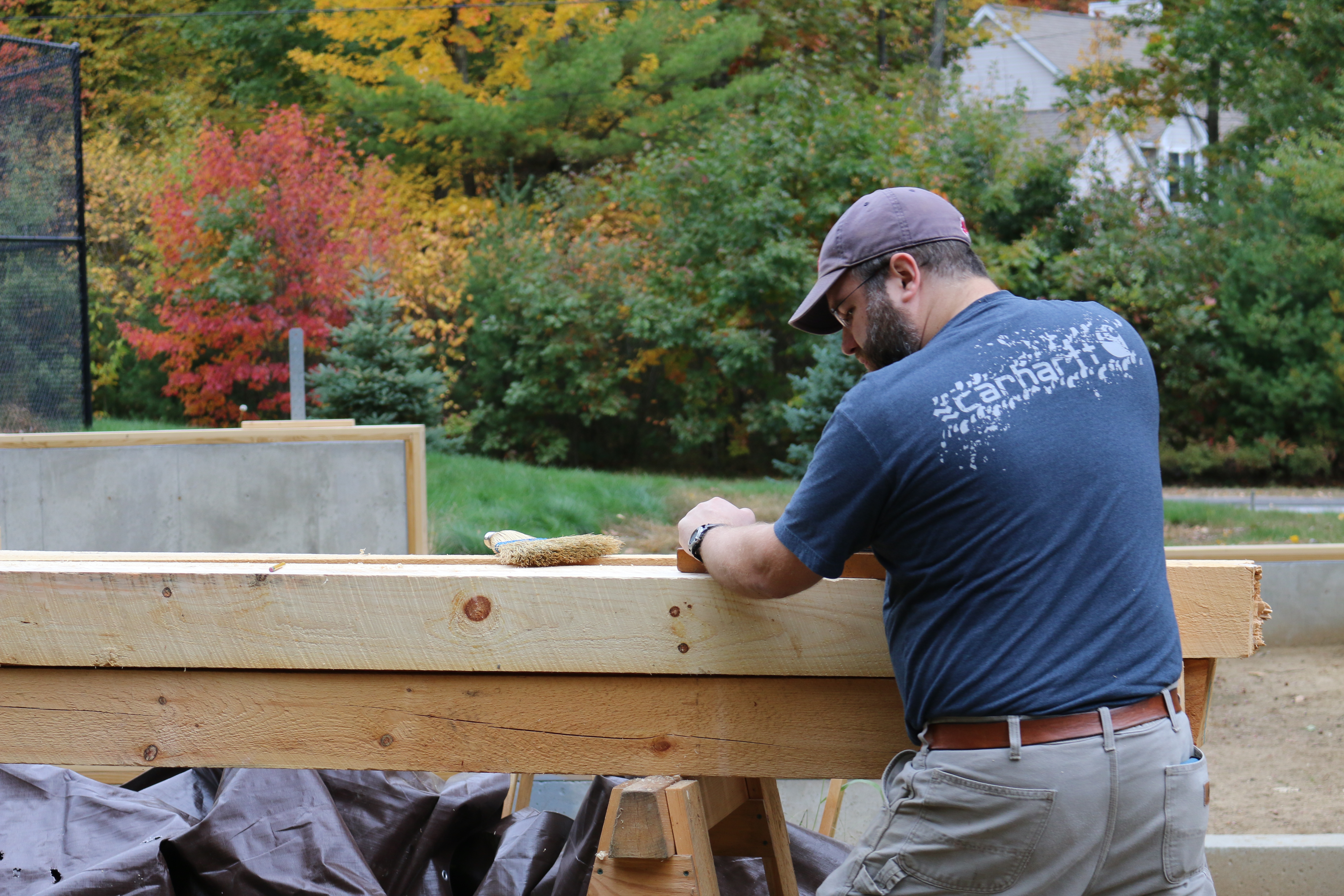
Bill using a traditional jack plane to clean up timber
For some timber frames I need to clean up and remove all the large circular saw or bandsaw marks. In a workshop or outbuilding being fresh from the mill is fine, but in a house all those rough surfaces can be a dust magnet or source of splinters.
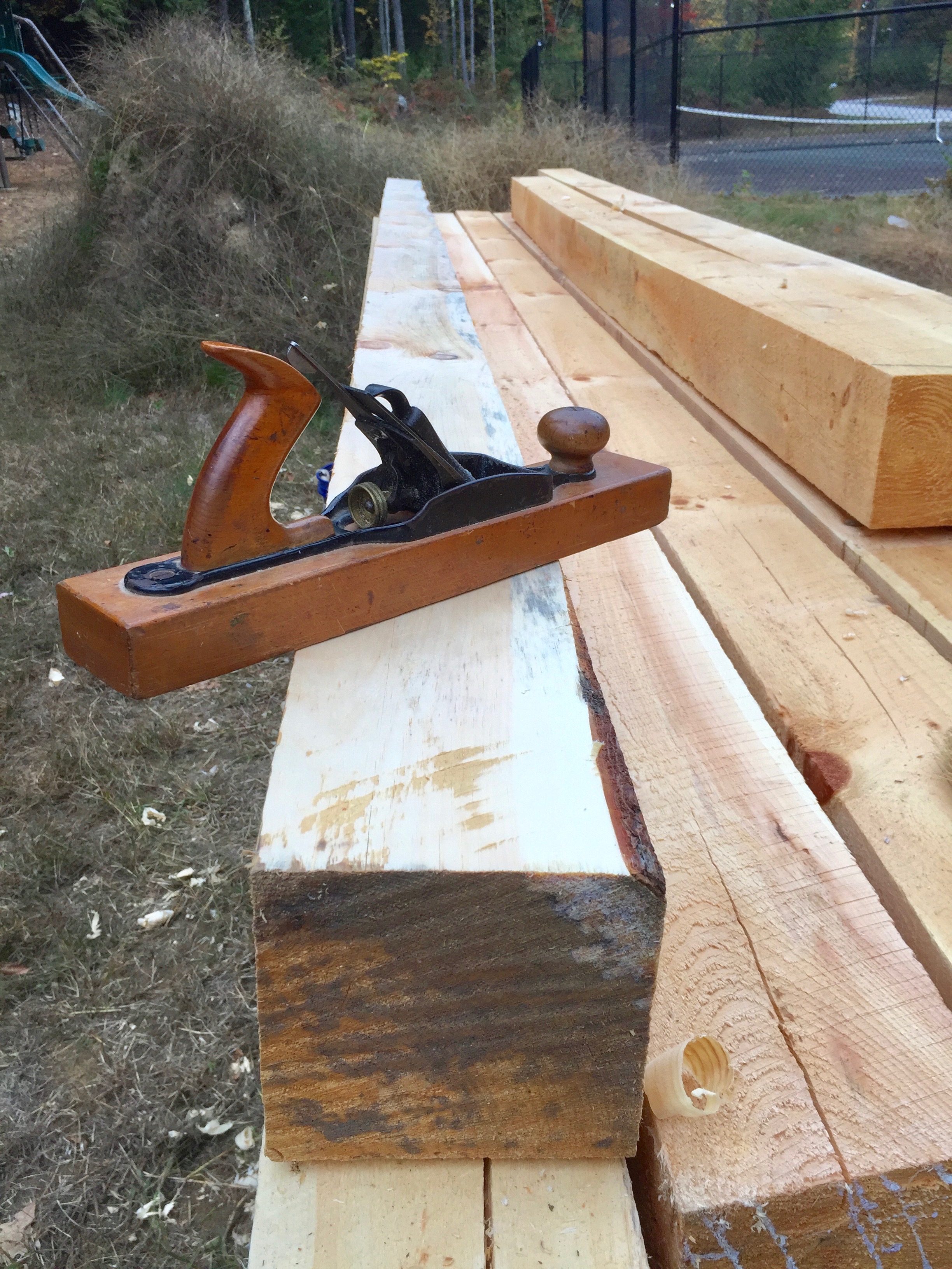
With a nice camber it makes quick work of dressing a green eastern white pine timber
On my jack plane I’ve ground a camber appropriate to a jack plane and take a reasonably heavy shaving. The work goes fast and I admit its fun to make a 25′ foot long shaving on some of the largest timbers.
At first I felt bad about using a plane from the 1870s for this sort of work, but if properly maintained it will have a surprisingly long life and I’d rather see this plane get used as opposed to being in a pyre or on a shelf.
At the end of the day I make sure to remove the iron and wipe it down with oil so it does not rust and I’ll usually give the sole a little more wax.
Transitional Jack Plane in its new habitat
I can usually find these planes in surprisingly good shape for $10-35. If you’re willing to take one with more rust on the mechanism or a replacement sole you can likely get it for even less or even free from some dealers if you buy a few other items. The next time you are at a tool swap you may want to take a second look at a transitional plane and score yourself a good deal on a solid workhorse for your own timber framing or green woodworking projects.
It can take a long time to make a tent fly — but it’s worth it.
What is a Tent Fly?
A fly refers to the outer layer of a tent or to a piece of material which is strung up using rope as a minimalist, stand-alone shelter. In basic terms, a fly is a tent without walls. Purpose-made stand-alone flies are also sometimes referred to as bivouacs, bivvies, tarpaulins, or hootchies. — Wikipedia
A few years ago I didn’t know what I tent fly was, at least not by name, but on one of my visits to Eastfield Village I saw a nice one that Billy McMillen built and used. On some visits to Colonial Williamsburg I also checked out a huge tent fly that Garland and Ted and the guys had and decided I wanted to build one for myself. I wanted a place to work on timber framing elements out of the sun and rain, a tarpaulin for when we have a party in the yard, maybe a craft fair or a re-enacting event.
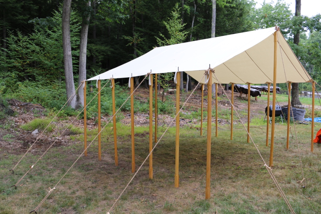
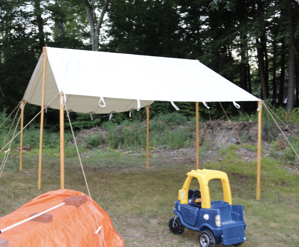
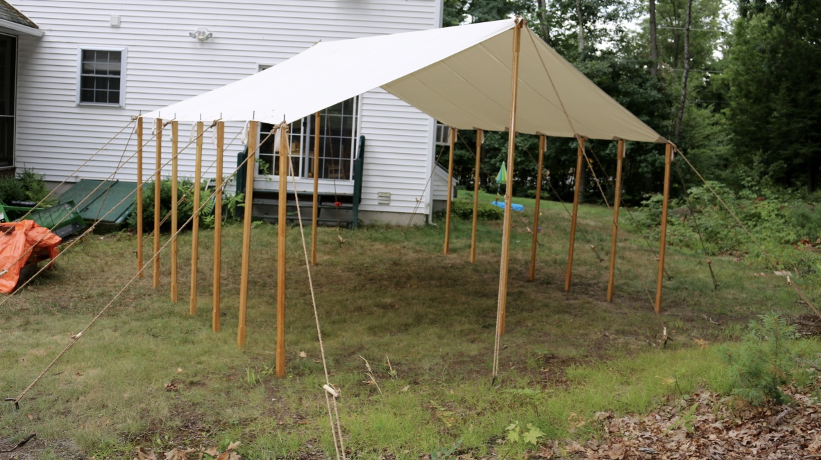
Tent Fly ready for use.
I decided to go with a custom made tent fly from Panther Primitives — an outfit Billy and Garland both recommended and big in the re-enacting community for making top quality tents. I went with the 12’x16′ Tent Fly with the 13oz Flame Retardant Sunforger Heavy Duty Canvas. I also had a special request to have grommets and loops so I could support the outer edges of the tent with a series of posts or a post and beams depending on how the fly will be used. I also ordered 16 manila rope sets, heavy duty stakes, a canvas bag for the ropes, bag for the tent and bag for the ropes. The folks at Panther were great to work with and make and excellent product — superior materials and craftsmanship.
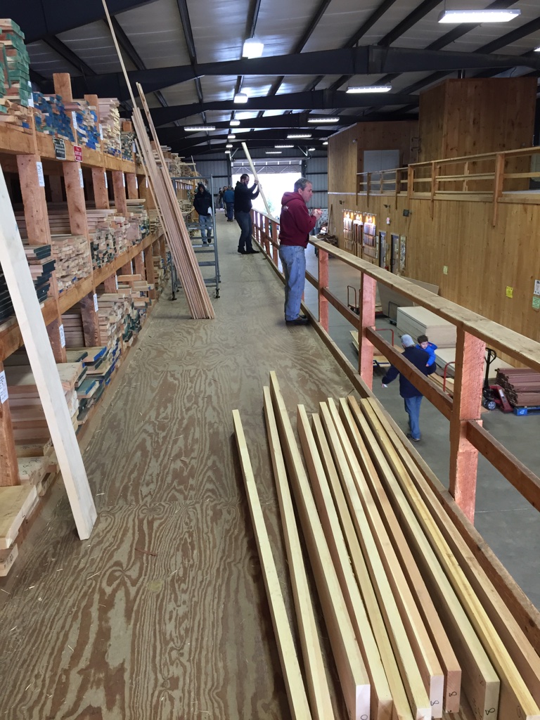
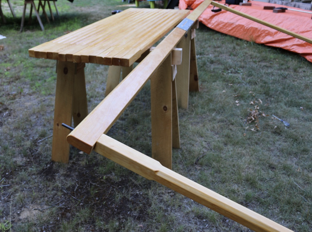
The project starts at the wood supplier — in this case Highland Hardwoods — my favorite.
With the canvas taken care of it was time for me to build the necessary posts to support this tent. Like any good woodworking project it starts at your wood supplier. I went to my perennial favorite — Highland Hardwoods in Brentwood NH. I carefully selected some straight grained 8/4 Eastern White Pine. I ripped the pieces to rough size, power planed and jointed each of the pieces and removed the mill marks with a hand plane.
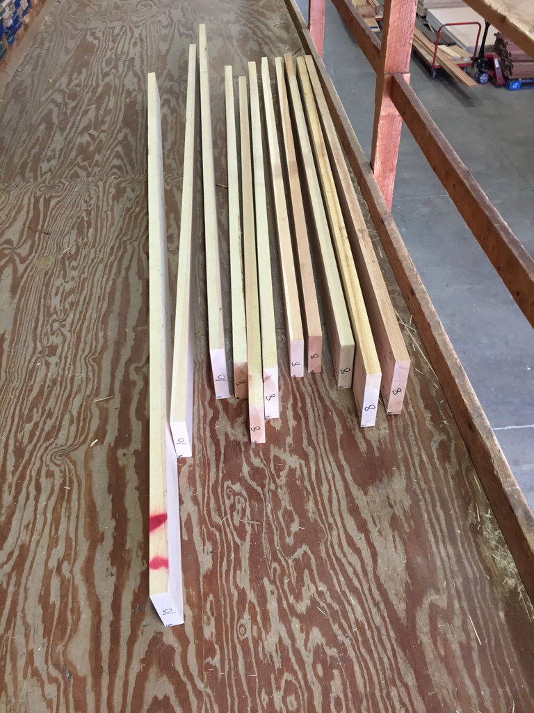
Carefully select straight grained easter white pine.
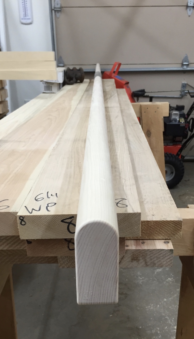
The center of the tent is supported by a larger beam –12.5′ long and roughly 2″x4″ — with a rounded over top. This beam is made from two pieces joined in the center with a simple metal connecting collar.
Stock getting ripped down to size and hand planed. Rounding over top of beam.
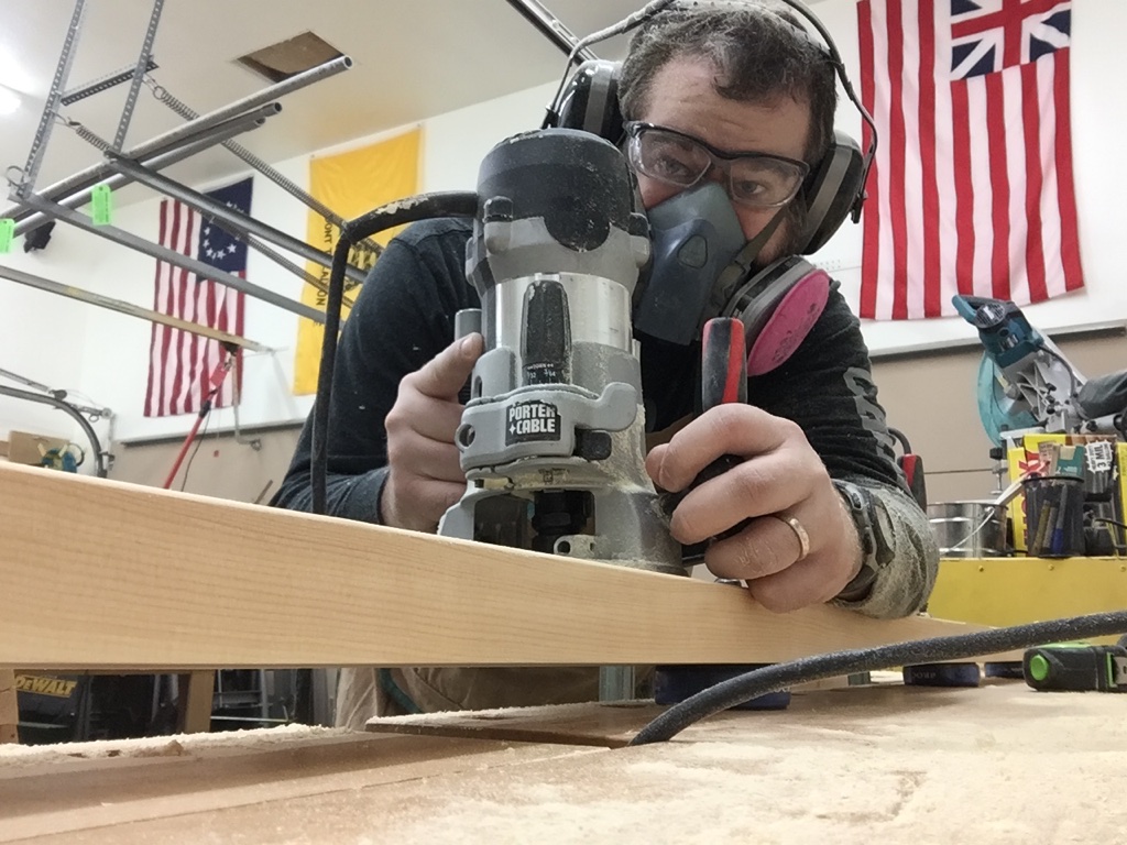
For each of the 2″x2″ upright support posts I routed in stop chamfers and used a 1/8″ radius rounding bit to break and square edges.
Creating stop chamfers on all the posts.
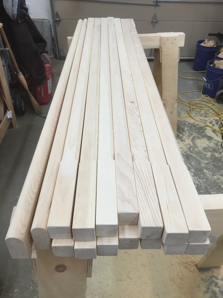
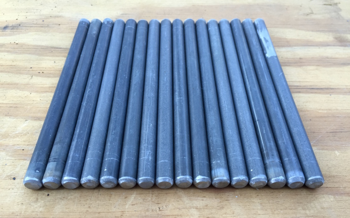
I then removed any mill marks from the routing. With 14 6′ tall posts and two 9′ tall posts it took a while to get all the woodworking up to this stage.
Shaping completed.
Next up was cutting 3/8″ metal rods to about 6″ long for each of the 6′ posts. The two 9′ tall posts needed 9″ long metal rods.
Rods cut with metal cut off saw and edges ground back on a slow speed grinder.
Once cut with an abrasive cut off wheel I rounded over the ends/corners of the rods on a slow speed grinder.
Ground rods for all the lower posts
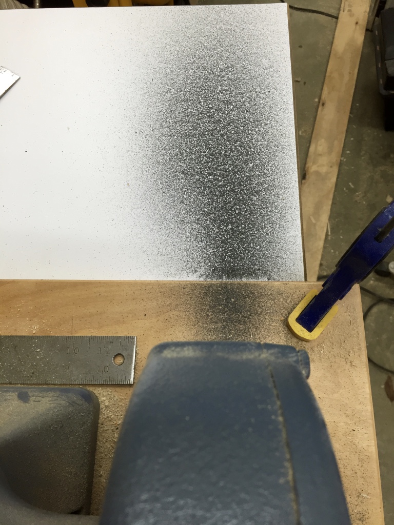
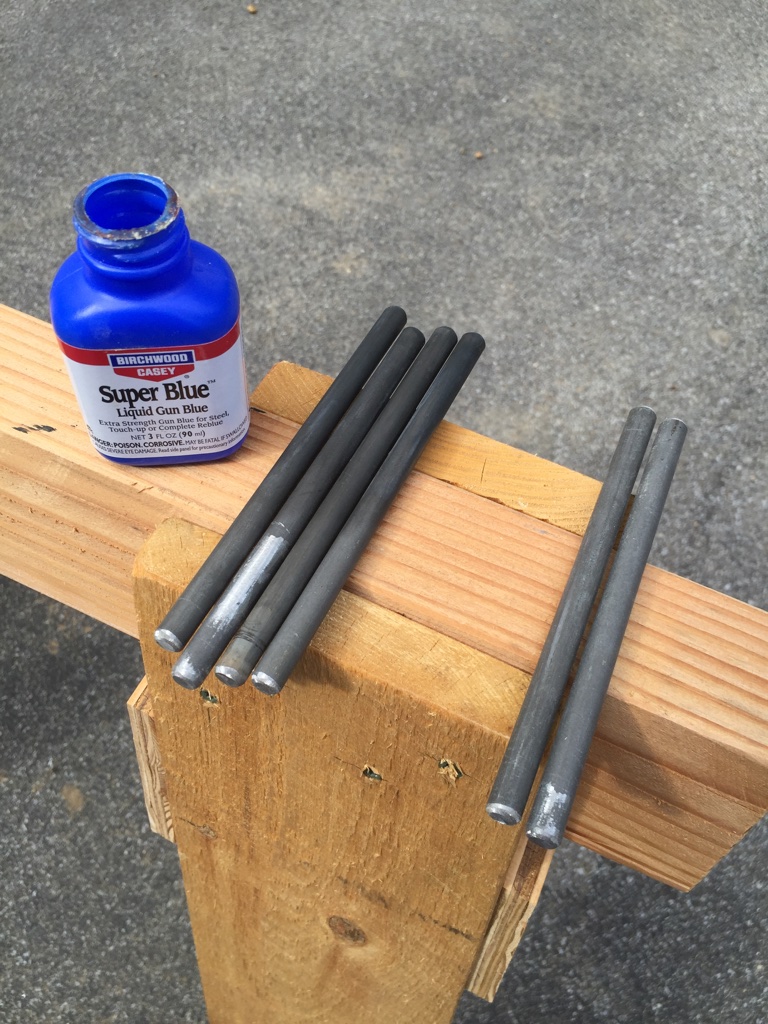
The mild steel rods from the hardware store are prone to rusting and have a bit of a modern look to my eye, so I cleaned them off with alcohol and then applied Super Blue (Gun Blue) to ends of the rod that would be exposed. The dark gray/black patina looked like older ironwork to my eye and at the least darkened all the freshly exposed steel from the cutting and grinding process. I’d also advise sealing it after that fact — with some lacquer or similar clear film finish that won’t react with he metal.
Using Gun Blue to give the the rods a black patina. (Left are blued and right are just cleaned with alcohol)
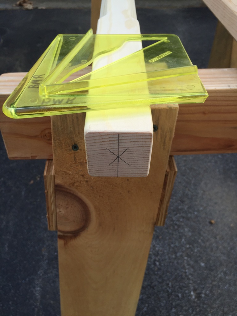
I used a center finder gauge to mark where I should be drilling a 3/8″ diameter hole, 3 inches deep into the end of the posts.
Marking centers on the posts
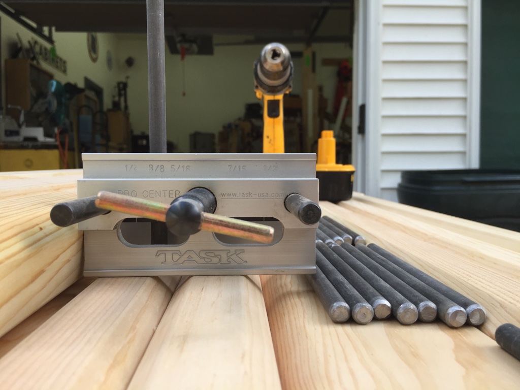
I also used a doweling jig keep the drill bit straight as I drilled into the ends of the posts.
Doweling jig used to center and guide holes drilled into the end of the posts.
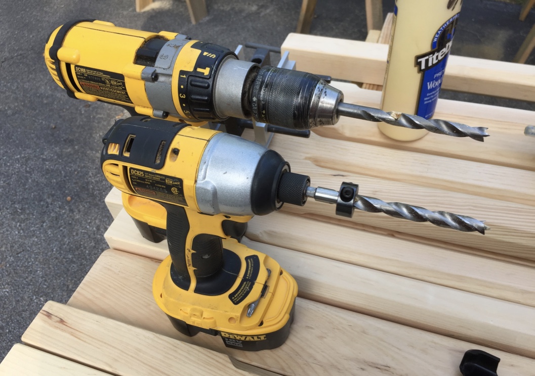
In order to accurately and repeatably drill to that depth and use the doweling jig which is pretty thick I needed to use two drills with the same size of bit. The drill (upper tool in photo below) is used with the jig to drill as deep as it will go. The drill is removed along with the jig. The impactor (lower tool in photo below) has a bit with an appropriately set stop collar to control the depth is used to complete the hole. The initial hole created using the drill and doweling jig provide a nice guide for the impactor + stop collared bit to reach the required depth.
(Upper) Drill used to drill most of the whole through the doweling jig. (Lower) Impactor (or second drill) with bit and stop collar used to complete the hole at the proper depth.
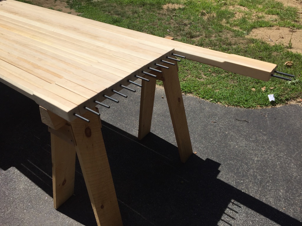
I then test fit/cleaned out the holes and glue the rods into place. (Make sure the blackened end is exposed). Ideally you want to use a high quality epoxy like the West System 2 part epoxy. I also installed tapered rubber washers from Panther that will help keep water out and keep the grommets where you want them on the metal rods.
Rods glued and inserted into the ends of the poles.
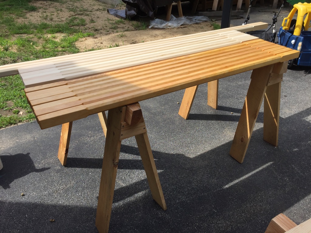
The freshly milled eastern white pine pine is a very pale white.
Applied amber shellac to give the pint some color. Followed this up with some UV stabilized satin water based polyurethane.
To give the wood a more pleasing color I gave it a coat or two of amber shellac. I then followed that up with two coats of a UV stabilized General Finishes satin polyurethane, sanding between coats as need.
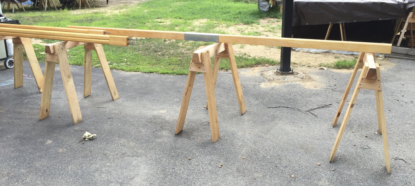
Fitting the metal connector to support the top beams.
With the woodworking complete it was time to join the top beam together using the metal bracket. Use two large pan head screws to secure the wood into the connector. Also drill two holes through the top beam for the pins to pass through.
Insert the 9′ poles into the center beam.
Insert the two 9′ posts into the vertical holes in the top beam. When I did the metal working I initially put the same 6′ metal rods into the 9′ tall posts, but realized the rod would not stick out the top of the beam, so I had to add 9″ rods to the other ends of the 9′ posts, but this worked out great as the accidental shorter rods now on the bottom of the tall posts help keeps the posts from kicking out when you are trying to stand up and secure the posts.
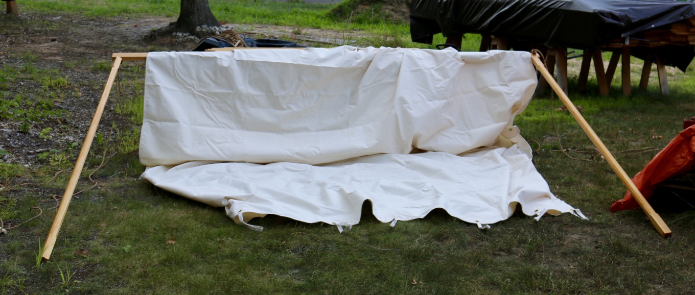
Drape the canvas evenly across the beam.
Drape the canvas over the top of the beam and carefully raise it to an upright position — you’ll want a helper for this. With the posts, beam and canvas in an upright position you’ll want your helper to keep it standing up while you secure the storm ropes — attaching them first to a stake you have to drive into the ground (with the stake angled away from the tent) with a heavy mallet, then to the rod on top of the post. Then use the wood block on the rope set to tighten up the rope.
Raise the center beam, secure the support ropes and set the exterior posts and ropes.
Next install the corner posts and install 2 rope sets on each corner deployed at 90 degrees from each other.
Work your way around the corner posts. (My 2 year old son already likes parking his little tikes pickup under it next to my saw horses)
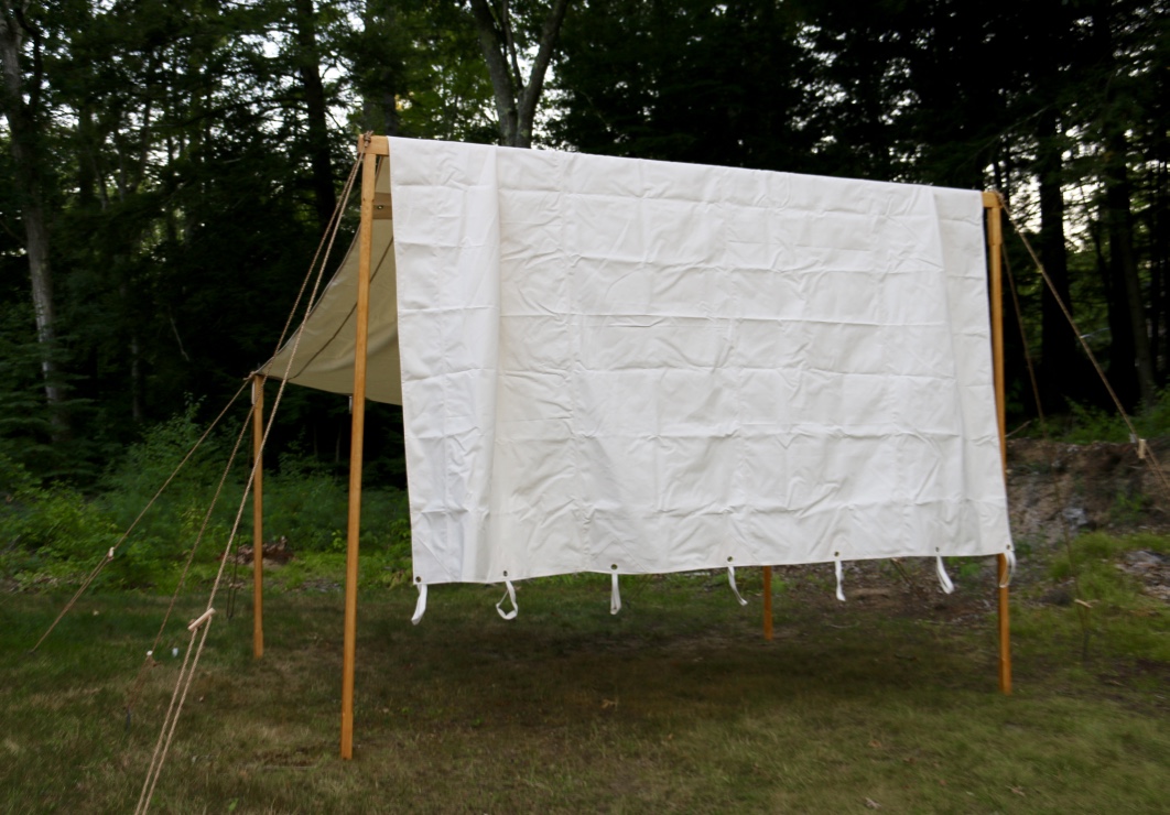
Then install any additional posts you want to use. I built enough posts to fill every grommet on the canvas. Every other post on the side of the tent also got a single rope set and stake to further anchor the test to the ground. If you find your self coming and going through the lower side of the ten you can remove 1 or more of those side posts to give you better access.
Completed test standing.
With a new canvas and rope sets you’ll want to check the ropes every day as things will stretch a bit and can get loose. Eventually they’ll stabilize and you can enjoy the use of your new tent fly.
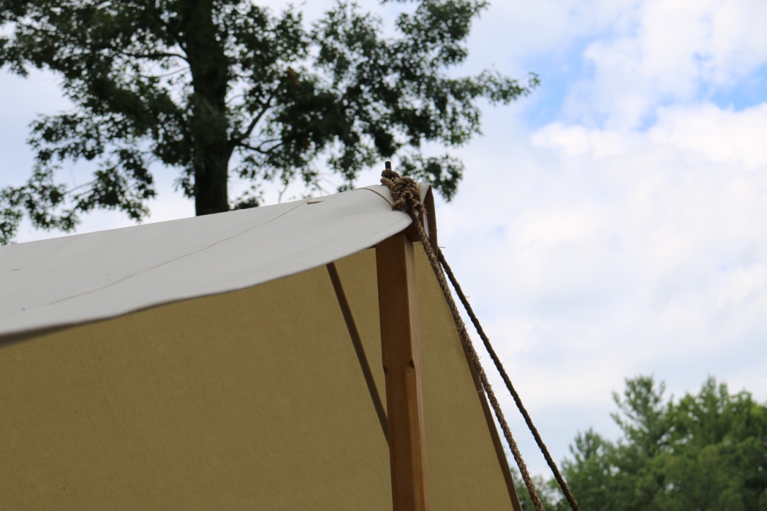
Storm lines at the ridge.
The 9′ high ridge beam and 6′ high ends are a bit higher than average but allowed me to walk in and out of the tent with ease and gave me a good size work space under the protection of the tent.
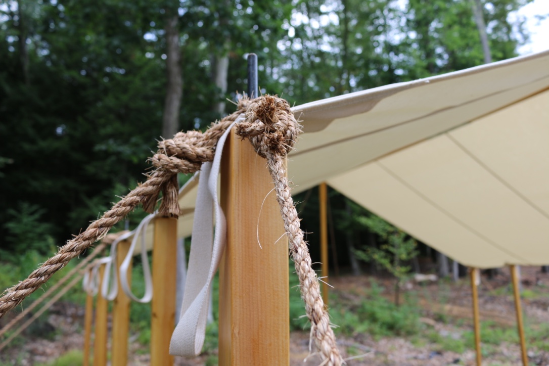
Tie down ropes secured.
It was a lot of work and a lot of fun to put together and I look forward to a long useful life for this tent.
Take care,
-Bill
P.S. If you build your own tent fly, please tell us about it in the comments below.
I’ve always wanted to make some Shaker Oval Boxes. I love a good challenge and learning a new woodworking skill. Back in May I attended the Early American Industries Association (EAIA) annual meeting which was held at Pleasant Hill Shaker Village in Harrodsburg, KY.
In preparing for the meeting I figured a nice set of Shaker oval boxes would be a solid addition to the EAIA’s silent auction.
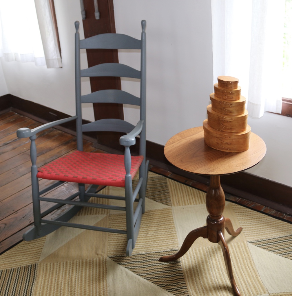
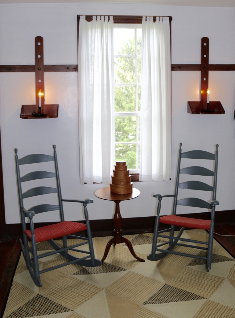
Shaker rocker, candle stand and boxes
In order to gather up the correct supplies and learn how to make a proper oval box I reached out to John Wilson of Michigan who is a well known expert on making these boxes.
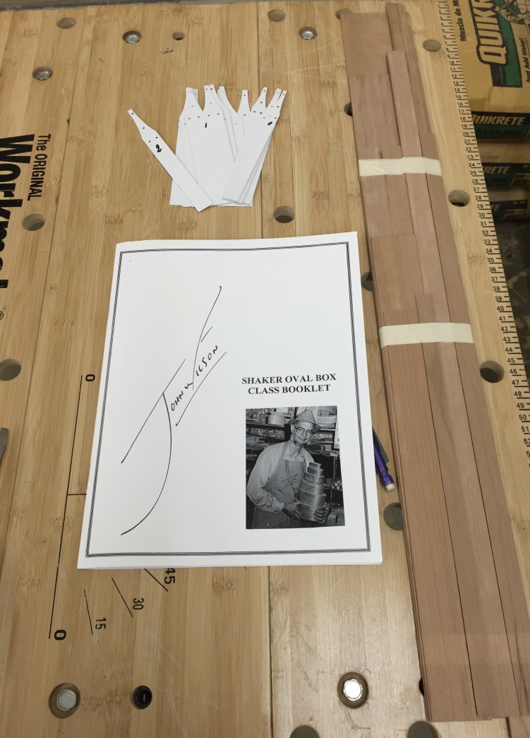
Templates, Guide Book and Band Stock
From John you can order an instructional DVD, book and templates along with supplies for the boxes and other related projects (baskets, trays etc). In this post I won’t go through all the steps necessary to make these boxes, but I will cover a highlight reel of some of the more interesting steps in the hopes it will whet your appetite for making some boxes yourself. (Links provided at the end of this post)
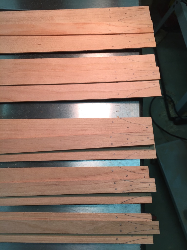
First off I laid out the templates for all the bands I wanted to bend into boxes and box tops. For this project I used Cherry. Then I pre-drilled the holes for the copper tacks.
Laying out template information on the band stock
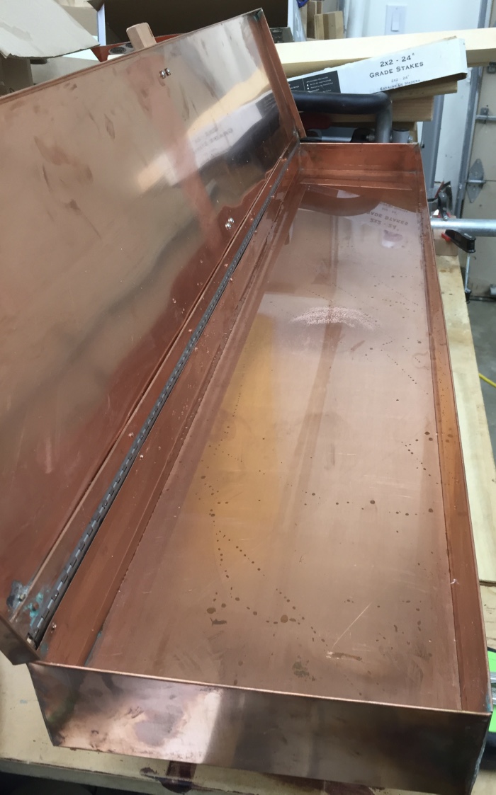
Next up was filling the copper steam box with water and heating it up. under the box is a double burner electric hotplate and blocks to keep the tray steady on the burners. When using Cherry you may also want to use distilled water as minerals in your tap water can leave some stains.
Copper steam tray
I then steam the ends of the bands, cut the tapers in the end with the tack holes and feathered the other end of the bands on the belt sander.
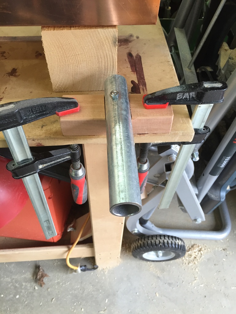
After letting the bands steam I pulled them out one at a time to wrap around the appropriate sized form and marking the overlap. Then remove it from the form and hold the band tightly in place at that same size marked while you take it over to the heavy round pipe anvil and clinch the tiny copper tacks in place to secure the band. This set of forms is a large block of basswood in the size and shape you want the box to be.
Bench mounted anvil for clinching the copper tacks.
I had never clinched a tiny copper tack before so I grabbed a shim and practiced with a few tacks of each size on the anvil. After a tack or two you’ll get a good feel for it.
Practice strip of copper tacks
I got a rhythm going and could feel/read how the tack was going in and move it on the anvil relative to my hammering to make sure I got the tack head nice and even with the surface and got a nice clean clinch on the inside.
Clinched side of practice copper tacks
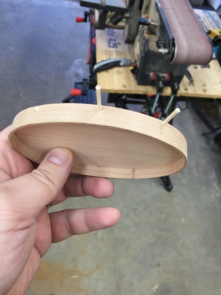
With the band tacked the next step was to get them over to the second set of forms to dry. These forms are two blocks of wood also in the shape of the box, similar to the first form, but these forms have a tapered edge profile and holes to let air/water in and out and give your fingers a place to pull the forms out from when they are dry.
The bottom band is steamed, tacked and setup on the second set of forms. The top band is wrapped around the bottom band on the form. The goal is to get a nice tight fit and line up the tack holes.
Bands steamed, bent around initial forms, then tacked and held in place to try by a second set of forms
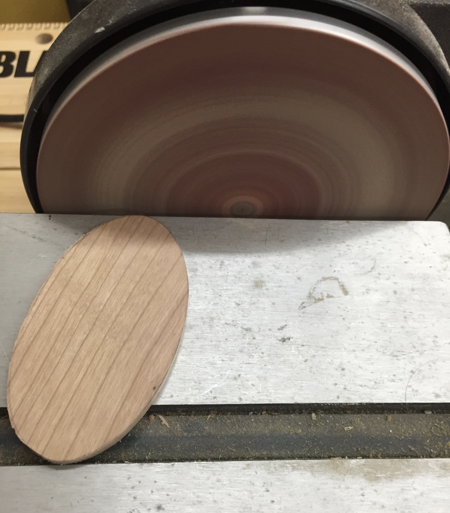
Let the bands dry for a day or two and then it is time to fit the tops and bottoms into the bands. Trace your band onto the top or bottom blank, cut it near the line on the bandsaw and then use a fixed disc sander with the table set at a few degrees under 90 and sand them to shape and test fit as you go. You don’t want any gaps or spaces between the band and the top or bottom.
The tops and bottoms are disc sanded at an angle and to the layout lines so they fit nice and tight
I got all the tops and bottoms fitted before moving on to the next step.
Fitted tops and bottoms
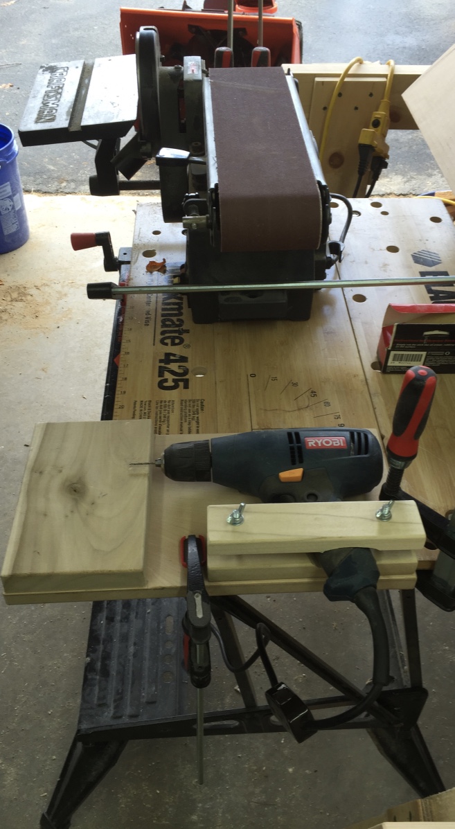
Next up was testing out a special drilling jig to make pin holes for attaching the tops and bottoms to the bands. There is no glue in these boxes.
Drilling jig for pins (Foreground). Belt sander and disc sander for cleaning up and fitting box tops and bottoms
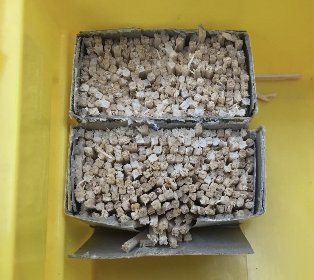
The pins that will secure the bands to the top and bottom blanks are made from hardwood toothpicks that are cut in half on a band saw.
Box of matches cut in half to be used as pins
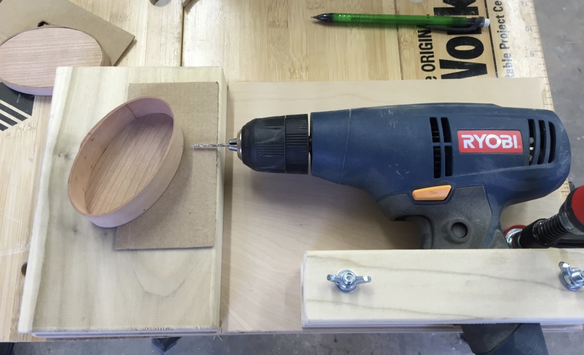
I made pencil dots where I wanted the pins to be, fired up the drill in this jig and made all the pin holes.
Using the drilling jig to make holes for the pins
For very tiny boxes with thin tops and bottoms I made a tape loop out of blue painters tape and taped some thin cardboard onto the face of the jig to center the holes in the thickness of the top or bottom of the box.
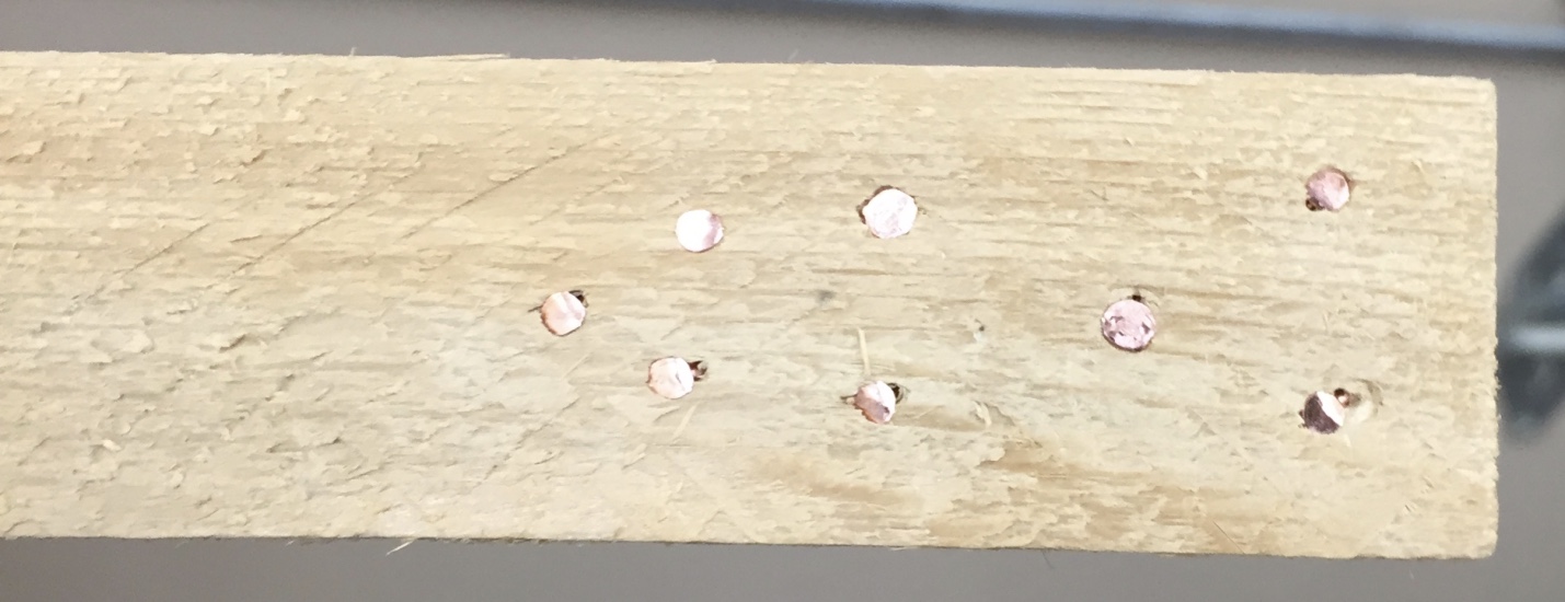
Fitting square pegs into round holes
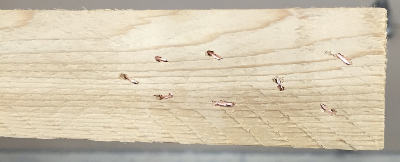
The pins are then tapped into place, clipped off and then sanded on the belt sander to remove any protruding pin left and make sure the bands are level with the tops and bottoms.
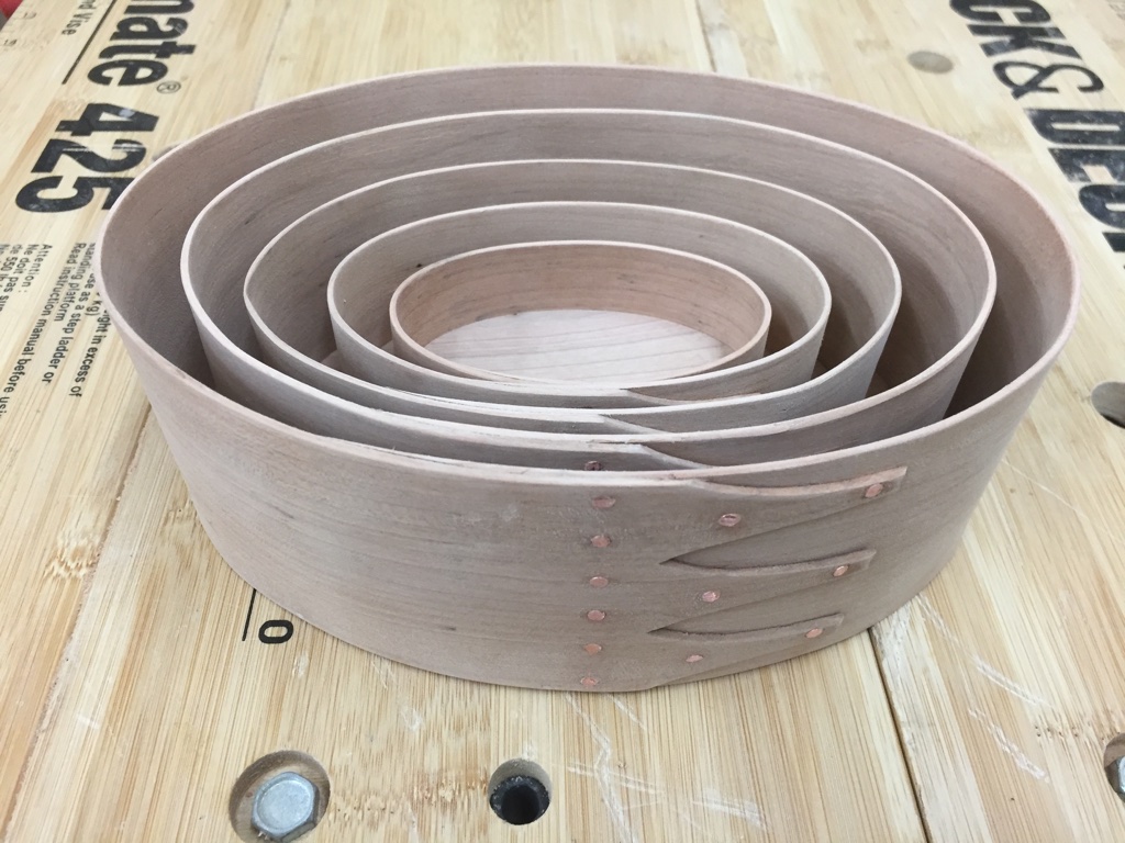
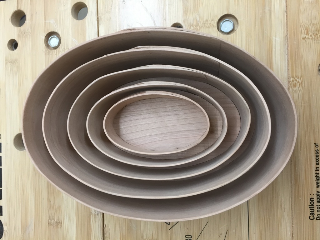
More Nesting
The boxes nest inside of each other similar to a Russian Nesting Doll. This made it easier to bring 5 boxes on the very long, and very full car ride from NH to KY with my wife, two babies and me.
Nested box bottoms
At this point the boxes all have a bit of a dull fuzzy look about them.
Fuzzy Boxes waiting for final cleanup
I gently hand sanded all the boxes and made sure the top and bottom fit the way I wanted. They should have a nice snug fit, but not too tight nor too loose.
Five boxes cleaned up and ready for finish
All the corner edges, and inside and out of the box get a final sanding and cleanup. Then time for the finish. I applied Tung Oil to the boxes to bring out the grain in the Cherry and finished it off with a couple of coats of amber shellac. Each box is also signed, dated and notes that they were part of the 2016 EAIA annual meeting.
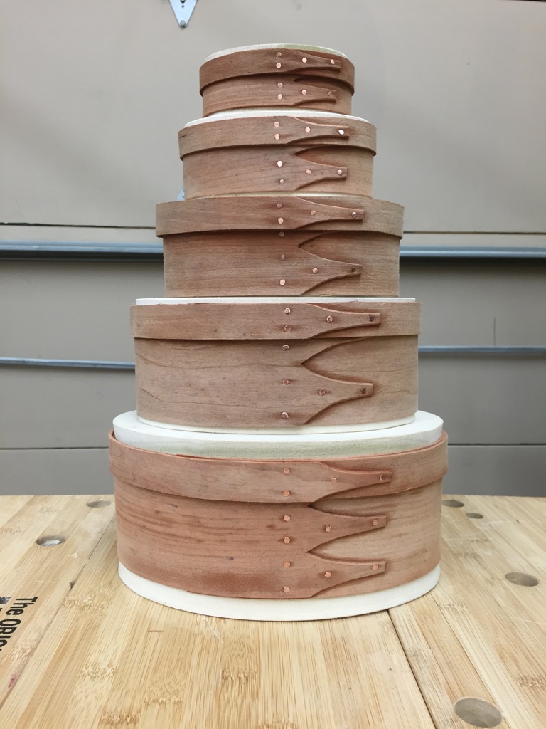
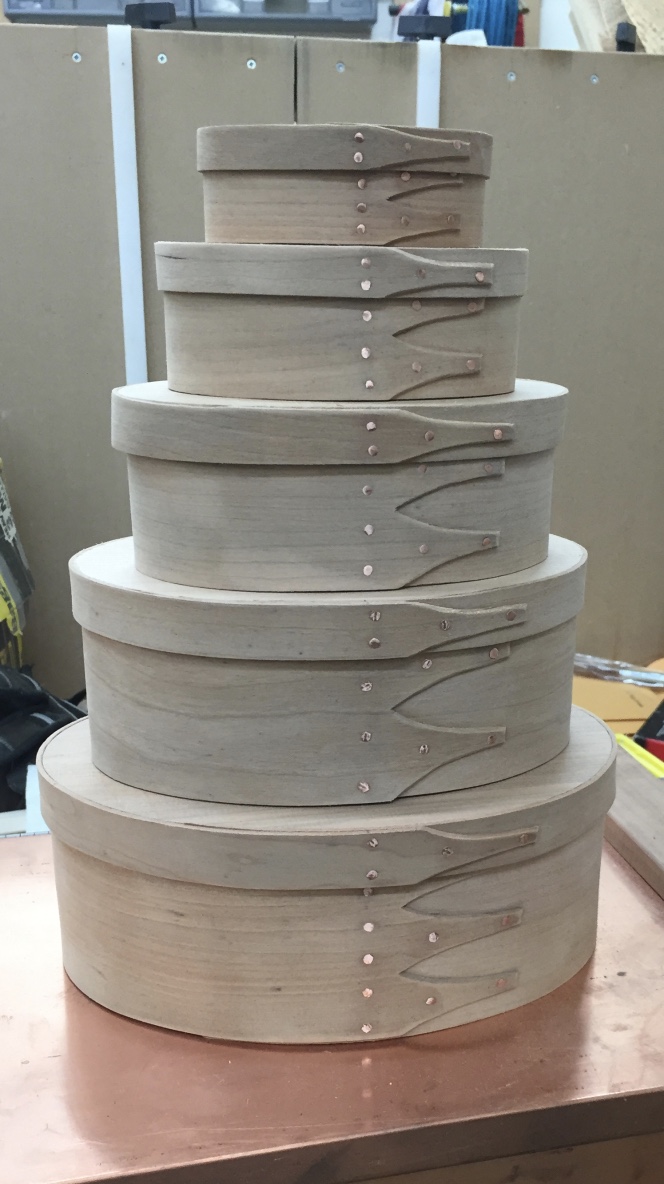
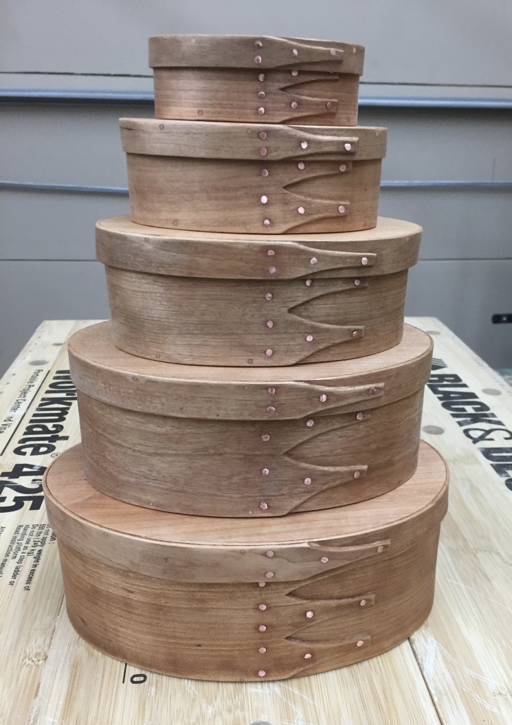
Finished set of boxes in sizes 0-4
I was very pleased with how well the boxes turned out especially given this was the first time I ever made shaker oval boxes.
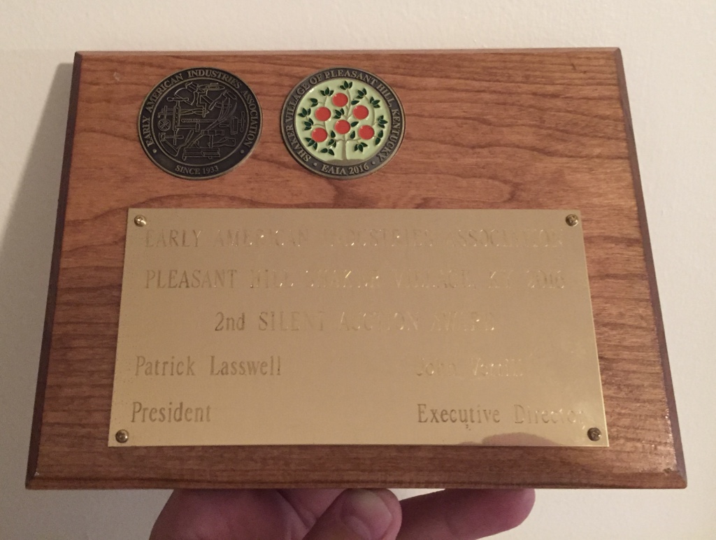
I was also glad to hear EAIA members also liked them as my set of boxes in sizes 0-4 turned out to be the second highest grossing item in the EAIA silent auction and I was humbled to receive the plaque below.
EAIA 2016 Annual Meeting Award, Second Place in the Silent Auction
I know they went to a good home, the home of Judy and Bill McMillen of Eastfield Village and Richmond Hill fame and good friends of mine. I’m also happy to report I was able to win the auction for some of the items Billy made as well including a Tin-Smithed dustpan my wife and I both had been wanting for a while when we saw one that Billy made at a prior event, but that is a post for another time.
Completed boxes in their natural habitat
I had a great time making the boxes and we all had a great time at the annual meeting. I had wanted to visit Pleasant Hill Shaker Village for a long time and I’m glad I finally got to see it and spend the better part of a week living in the village.
If you’d like to make some Shaker Oval Boxes of your own, please check out the link to John Wilson’s website below along with links to more information on Pleasant Hill Shaker Village and the EAIA.
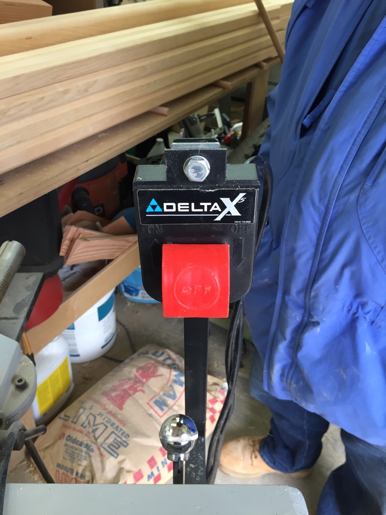
It’s never a good day when a power tool gives up its magic blue smoke. When I was making a recent run of saw horses my jointer’s switch decided it had enough.
It’s a Delta X5 ‘Professional’ 6″ jointer with the 42″ beds. It’s the same one that had the large fence advancement knob break a while back requiring a modern make-do sort of fix. For what was supposed to be a top of the line ‘professional’ machine for its size I’m disappointed with how many issues it has had related to the manufacturer cutting corners. I used to be a big fan of Delta but in recent years and especially with it being sold off from Pentair and later Black and Decker and the turmoil with it being owned by an overseas company that only seems to own some of the old Delta product lines I’ve been disappointed with the quality and longevity of these machines compared to the old iron 20th century versions of the same model tools.
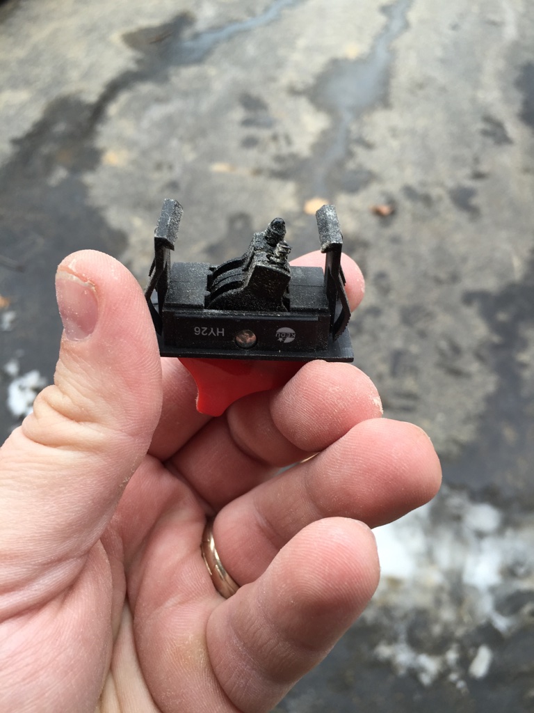
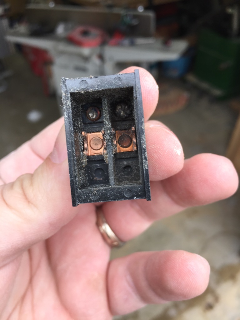
Fried lead
I knew this switch was going to be trouble the minute I saw it in person as I have a Delta 36-980 Table saw of the same vintage and both purchased new in the late 2000s — that had the switch die — at least in that case of fused into the ‘On’ position so I was able to add a Rockler Router Table Switch with a nice big crash pad on it and have a safe and reliable way to turn the machine on and off.
For either machine they want $50-65+ for a replacement switch assembly that likely would not last any longer and has an incredibly cheap feel to it. I didn’t want to hack the cable and try and hardwire in a similar Rockler switch on the jointer as the flimsy arm to hold the switch would require even more modifications.
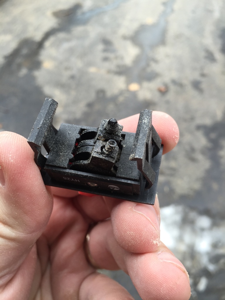
Notice the now much shorter contact
When the switch decided to die it seems to have arced and burned up the contact inside the switch (As seen above and below)
Carbon on the contact (sawdust from leaving the broken part sitting around the shop for a while)
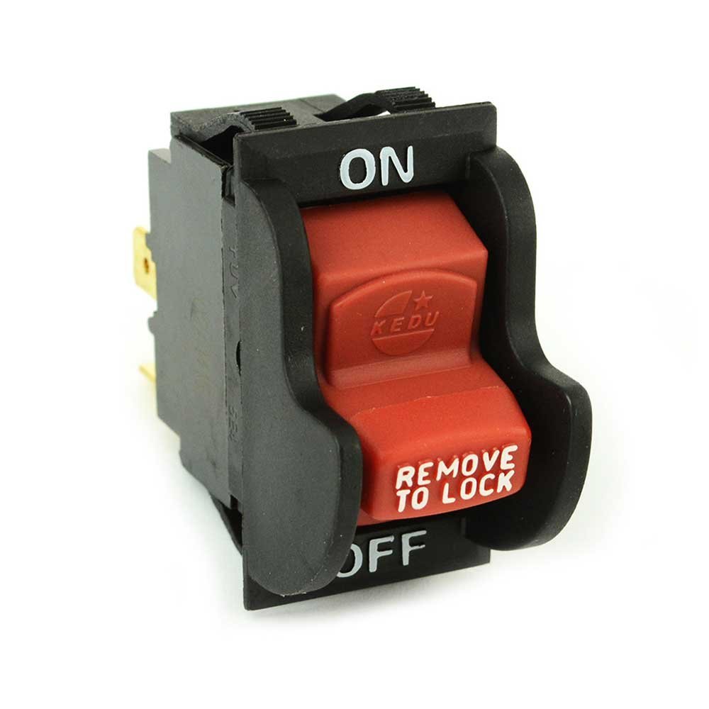
Rather than throwing more good money after bad I figured with some research I could find another switch to insert into the housing that would have the same load ratings and have a much lower price and it took a while to find one I thought would work, but eventually I found the switch below:
Replacement Switch
At the time I bought it, they cost me about $10 each and I bought one for my jointer and one for the table saw. You can find this toggle switch here on Amazon.com
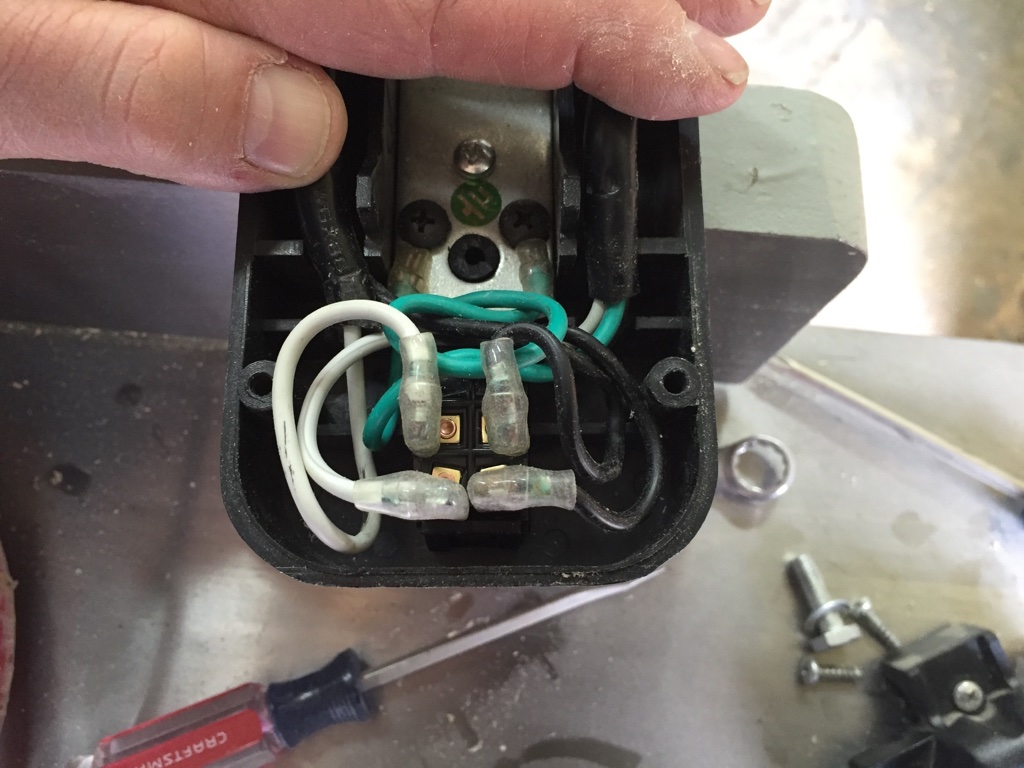
Take a photo of your wiring ahead of time
I opened up the housing, took a picture of the wiring via my phone so I could wire it back up correctly, unplugged the leads and compressed the snap fittings so I could pry the old switch out. The new switch popped in and the contacts fit fine. I neatened up the wires, gave the circuit a quick test and closed up the housing and put it back on the machine.
Delta X5 Jointer Switch Assembly
The replacement switch also has that built in child safety switch/pin that can be removed and seems to work fine with that large over button as seen above.
With a little bit of research I’m happy I was able to save a few bucks and get this machine back into service. Hopefully this new switch from another manufacturer will last longer.
Take care,
-Bill
P.S. I know I have been slow about posting lately, but we just had our second baby and things have been very busy. I’ve been amassing more content from time out in the shop so for the next month or two likely posts will be coming out at a slower pace but I’m working to get through the back log.
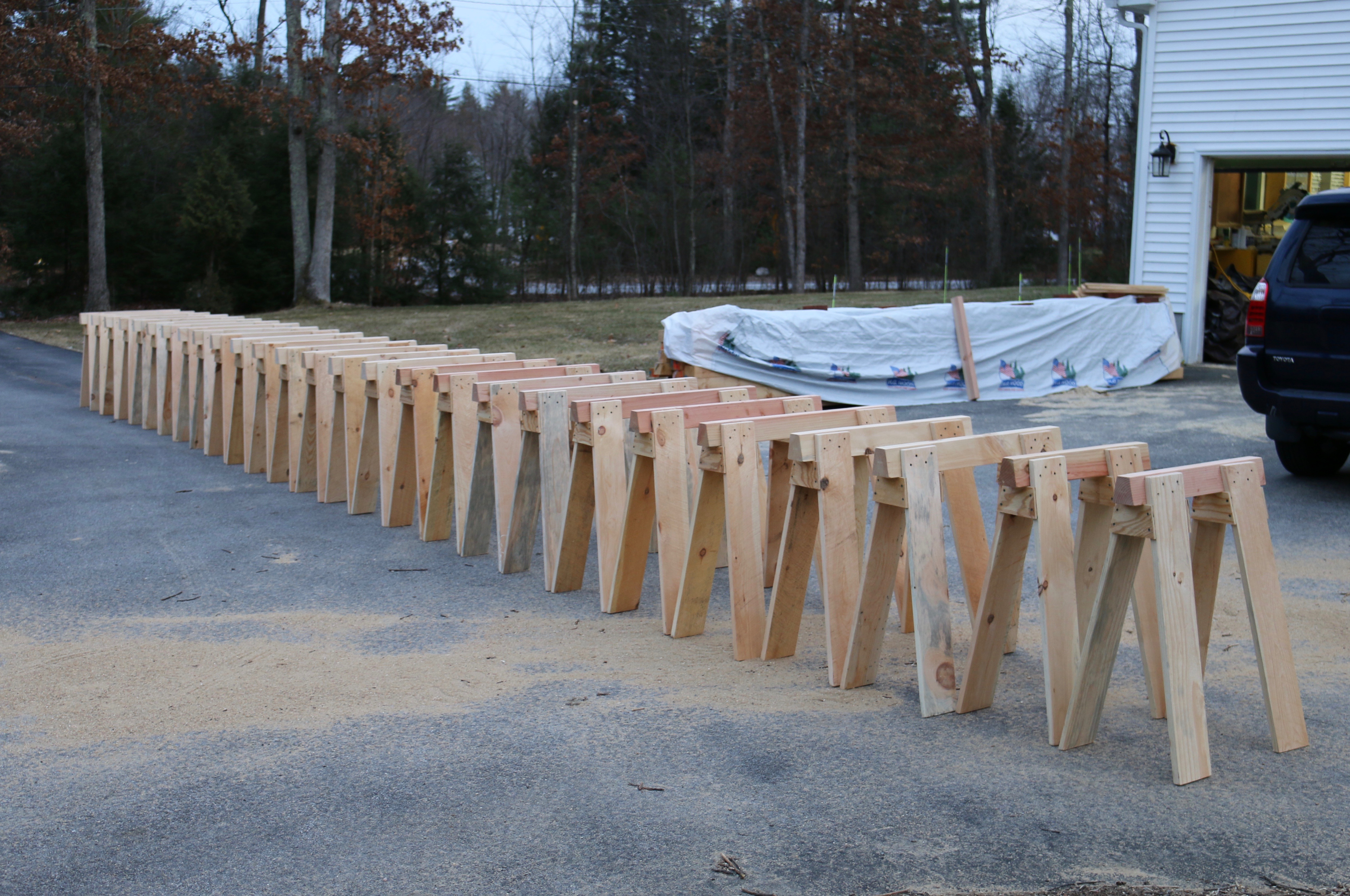
The best saw horses cannot be bought in a store, you have to build them. I’ve seen plastic saw horses bend and buckle under < 200 pounds of load. I’ve seen 2×4 saw horses with sheet metal couplers deform and crush.
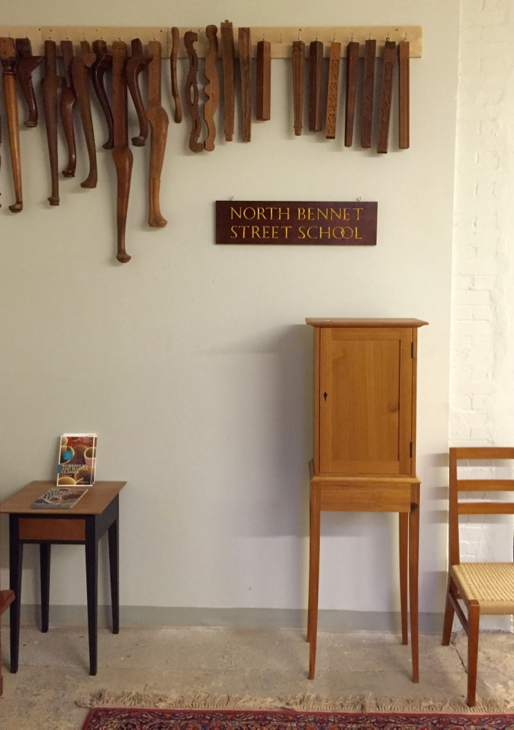
When I was a student at NBSS one of the first projects we completed was building a pair of solid wood saw horses that could meet the heavy demands of a preservation carpenter. The school would load them up with more material than I ever thought a simple horse could hold. I was so impressed with how well they turned out I built 10 more while I was there and they have served me well over the years.
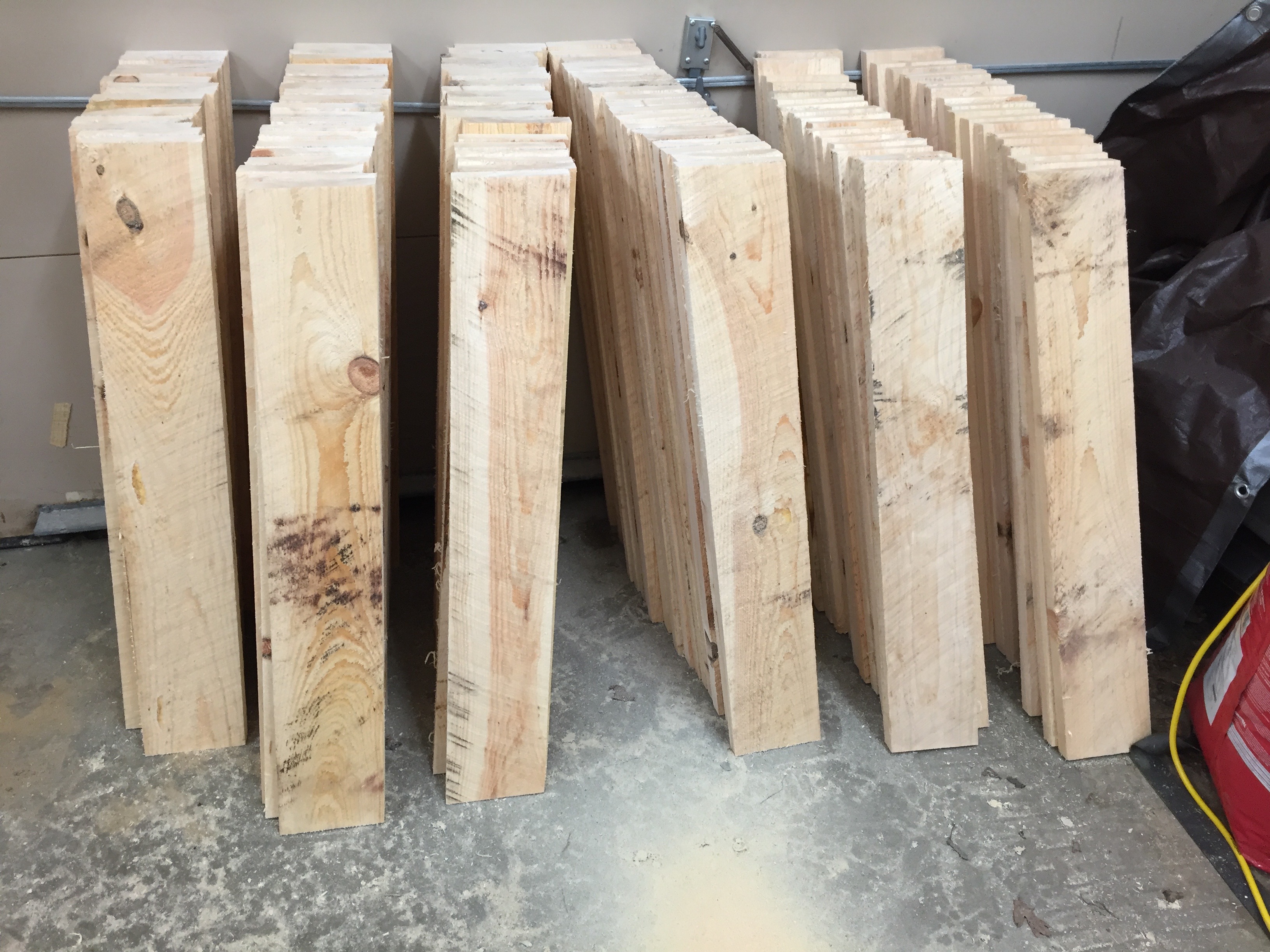
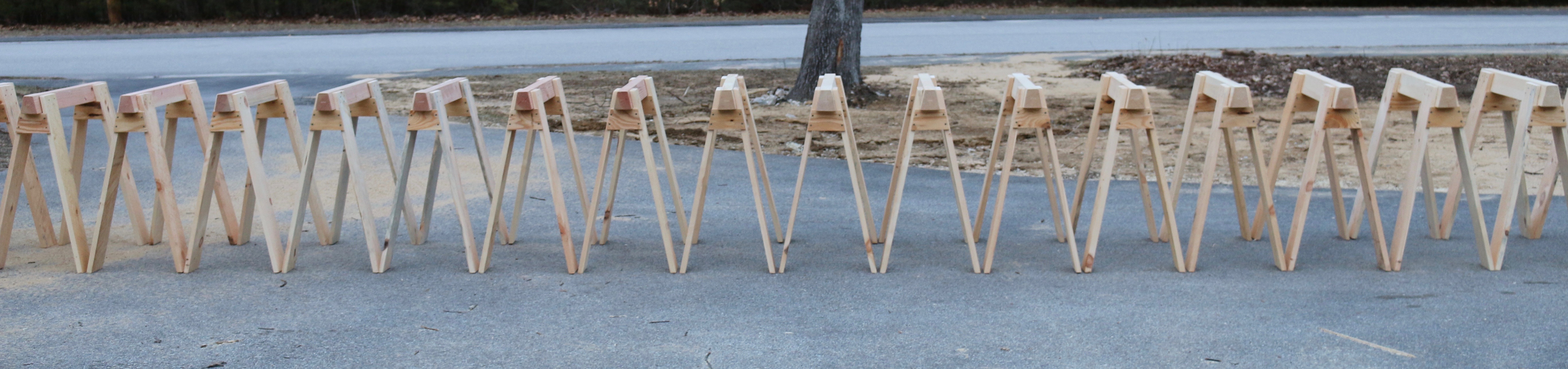
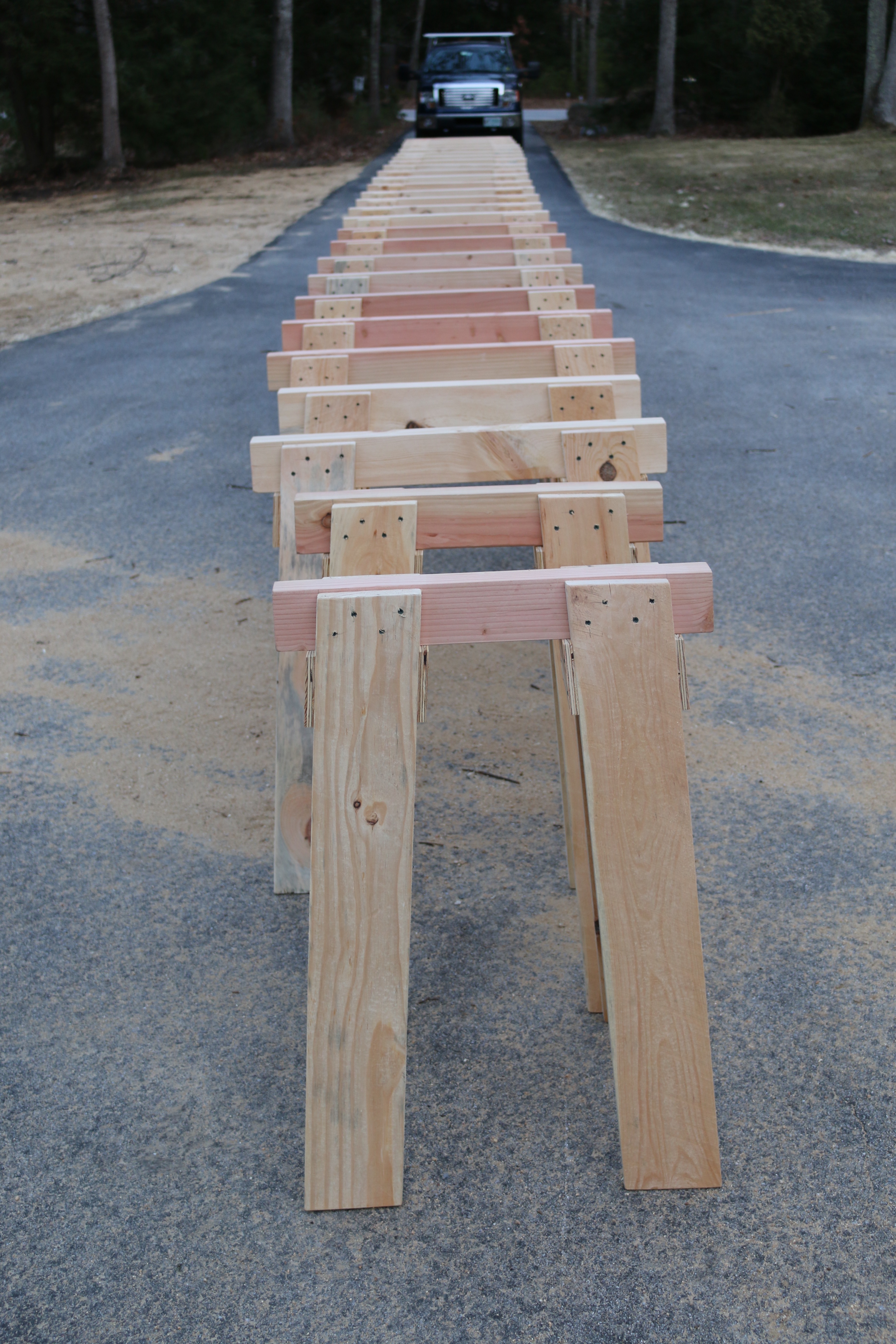
28 horses out on parade
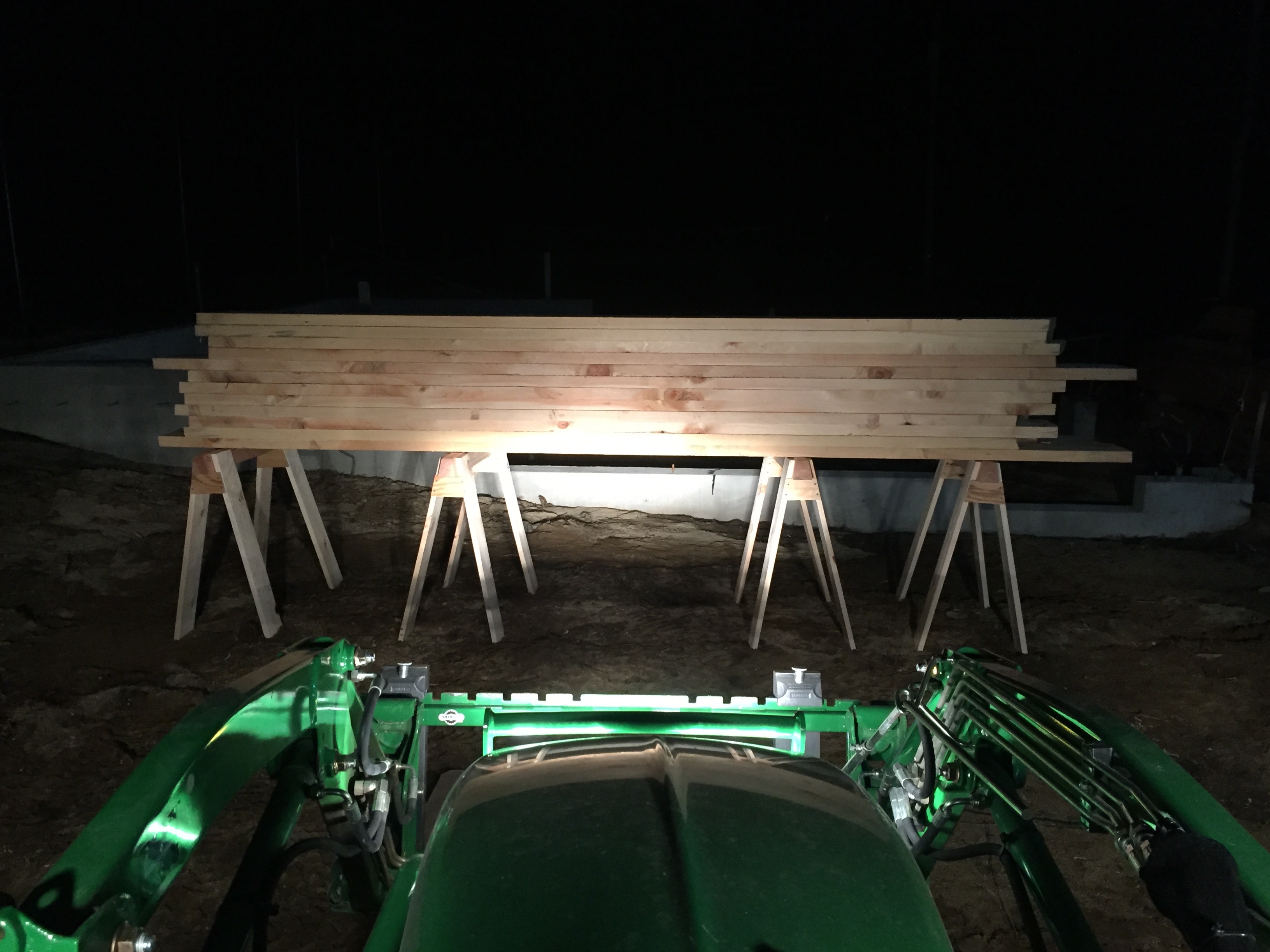
Right now as I build a 24’x30′ timber framed barn out in the yard I built another 28 horses to hold all the timber off the ground for sorting and working through the piles. The post below covers how I built these heavy duty horses.
For a large run of horses like this it is important to run through each operation like a small assembly line, though at times it can feel like a slog — after cutting 112 legs you become a master at optimizing all of your operations.
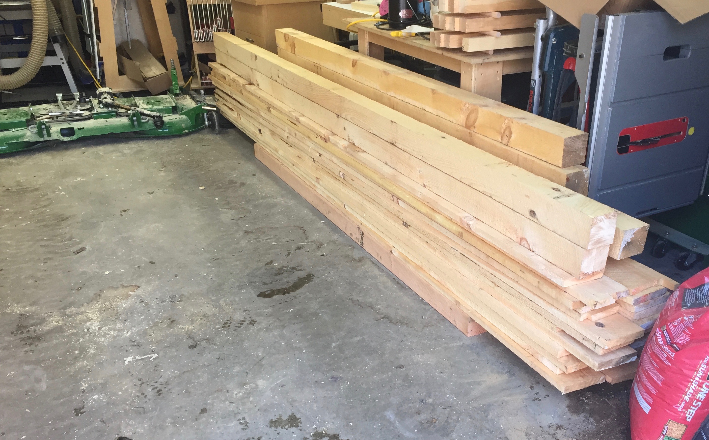
Large pile of green eastern white pine ready to go.
The wood of choice is green eastern white pine we buy from a local sawyer/lumber company. (Copeland And Sons Lumber). The beams (the work surface of a horse) is cut from a 4x4x12′, the legs are made from 1x6x12′ boards and the gussets are made from 1/2″ CDX plywood. Buying rough green stock like this from a sawyer helps keep the price per horse reasonable and the wood is full size, not nominal, so my 4×4 is 4″x4″ when I get it. I estimate that they cost me < $10 each in terms of materials.
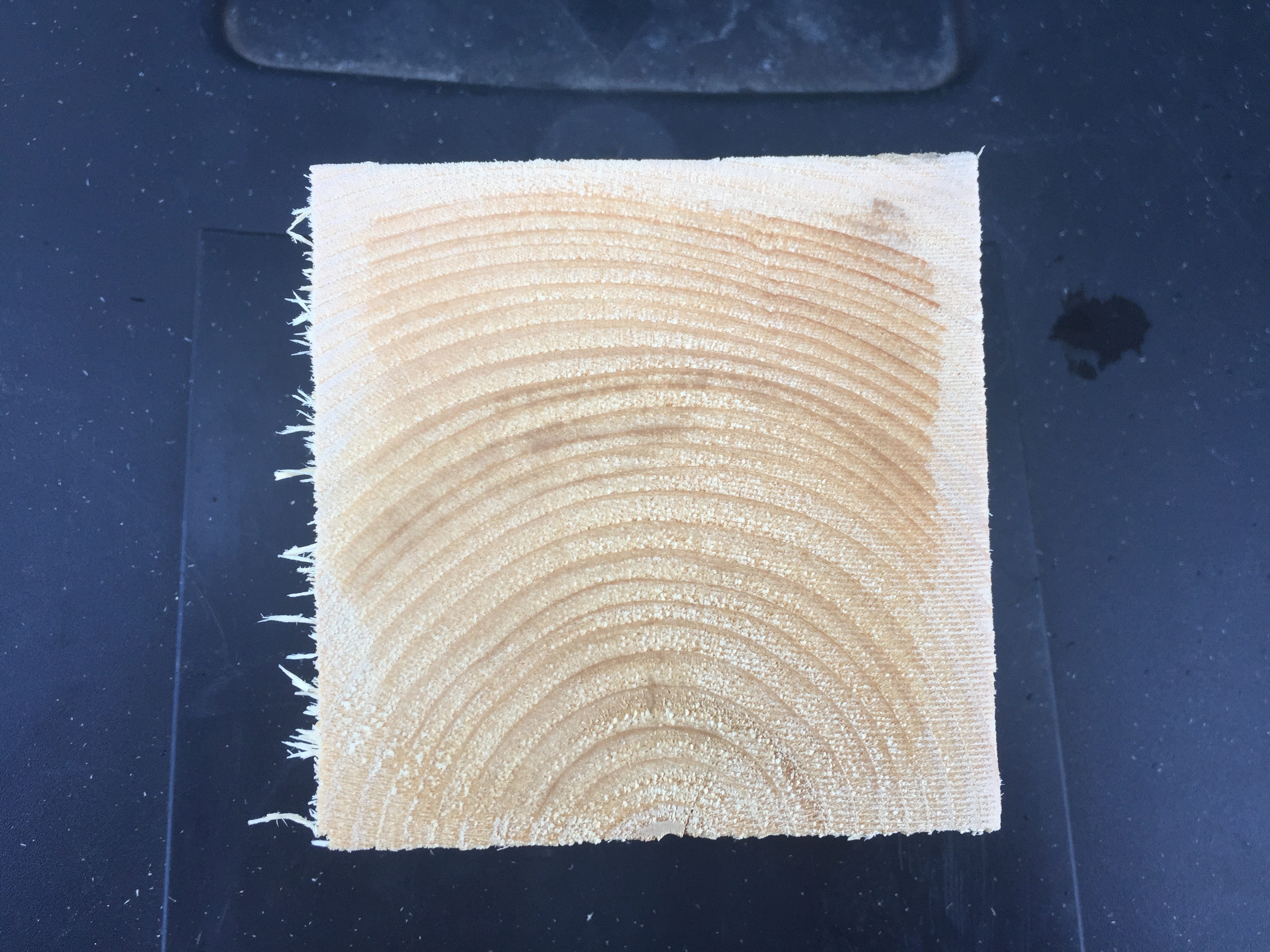
You can see how much moisture is still in the 4x4s
A note on working with green lumber, for horses or timber frames or similar projects — this wood was a tree possibly only a day or two before I get it, so if you use a power tool you may get some water spray on you. Be warned. Also make sure you wipe down and oil your tools appropriately so they do not rust. In the photo above you can see the outer 1/4″ or so that has dried a bit vs the wet center on this fresh cut off piece.
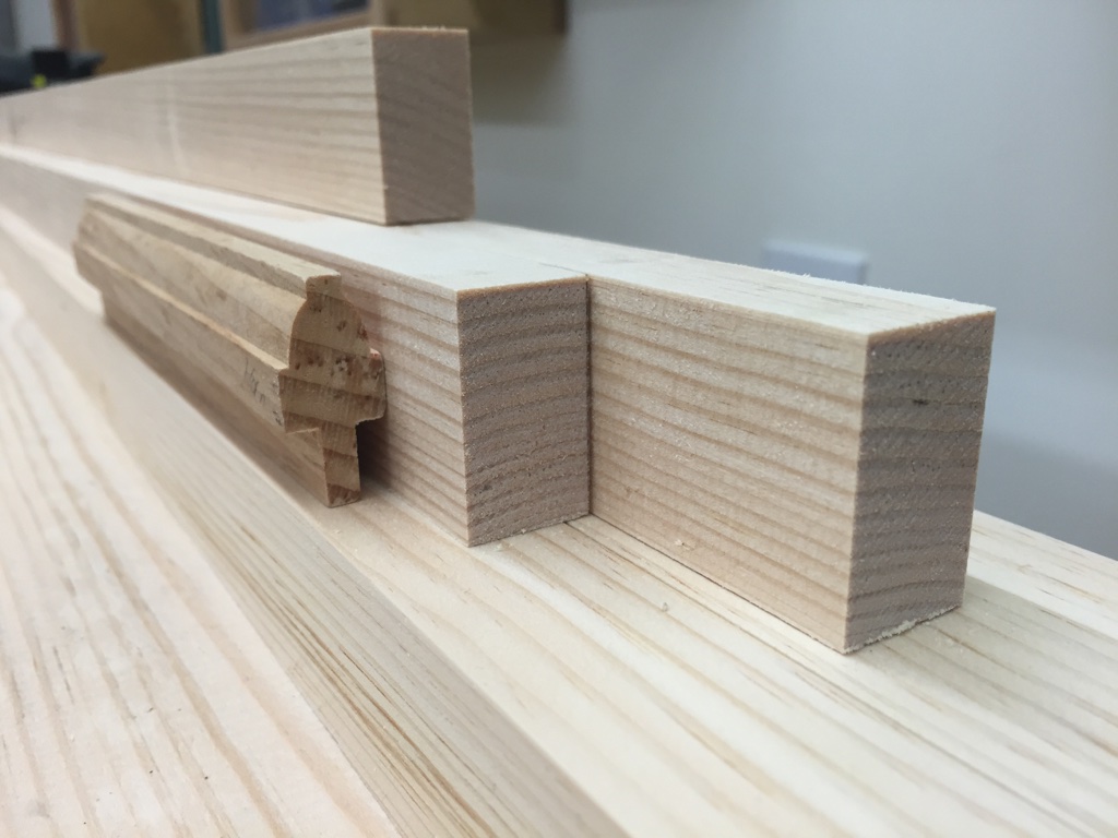
Stack of cut beams
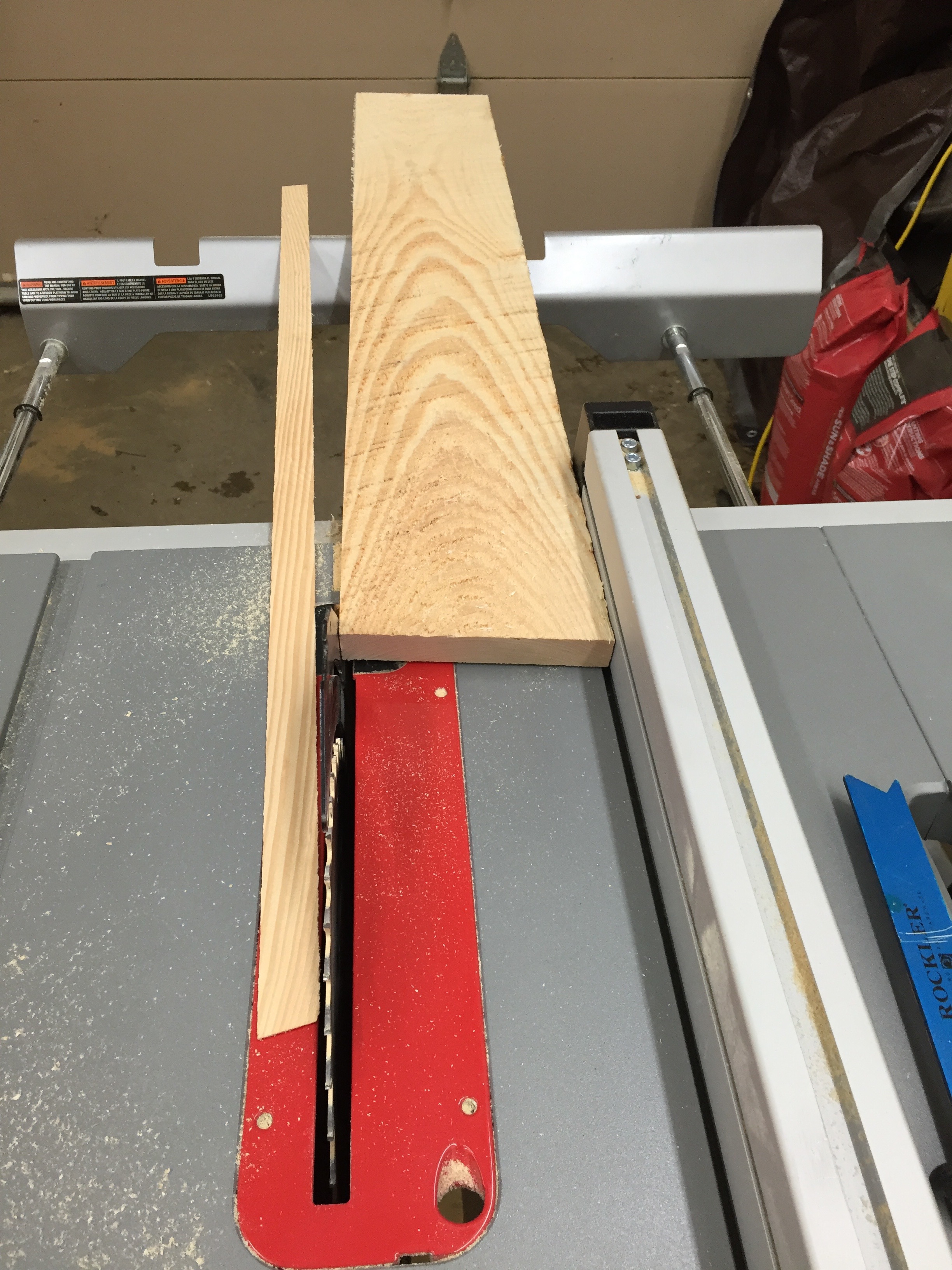
I start by cutting the beams to 36″ long. I then cut a 12 degree bevel on two sides. If your table saw cannot cut a full 4″ on an angle you can cut as much as you can, snap off most of the waste and then use a jointer or portable power planer (like 3-1/4″ Makita Door planer) to even out the side.
I also stamped my name into the end grain of each beam with my name stamp. It makes it easy to tell my horses apart from say another friend from the school.
Beam and gusset with dimensions. I also used my namespace on the beam end grain.
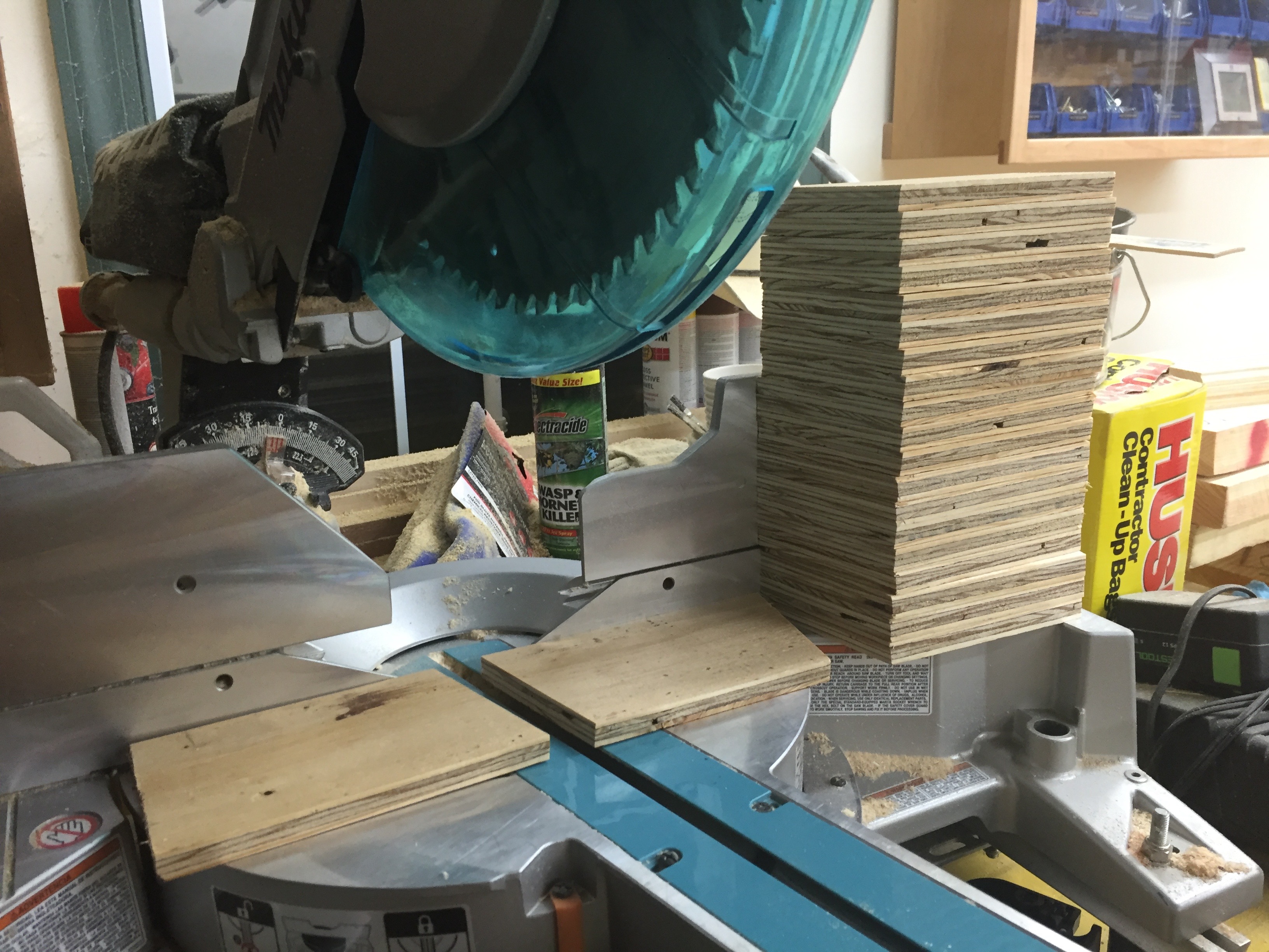
Next up I ripped my 4×8 sheet of 1/2″ CDX plywood into ~4″ wide strips. I then took a second pass on each strip with the blade set to a 5 degree angle. This allows the gussets to nestle up tightly against the beam during final assembly.
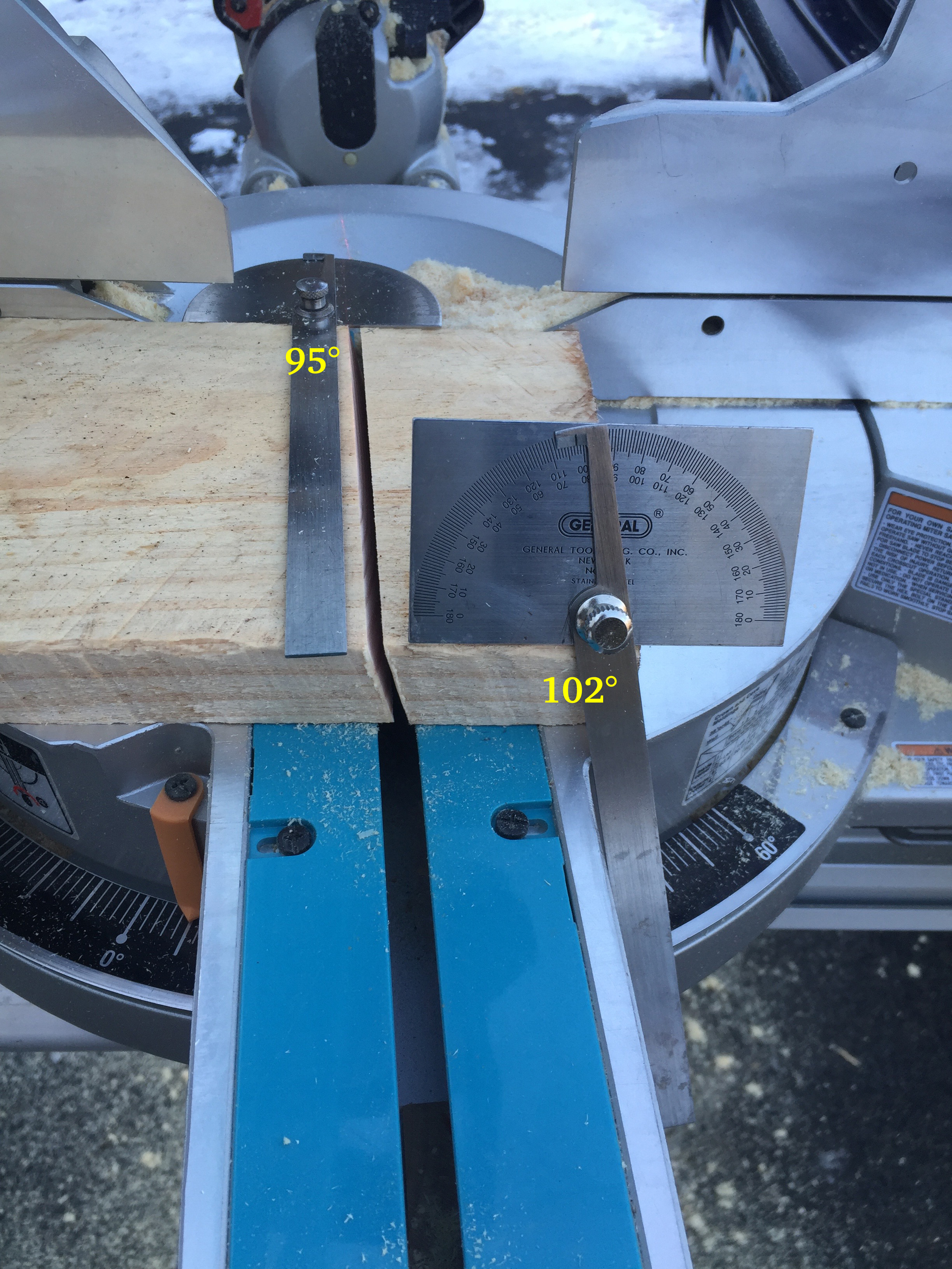
Cutting compound angles for the legs. 5 degrees and 12 degrees.
Next up I cut all the legs. I set the compound miter saw to cut at a left tilt of 5 degrees and a right rotation of 12 degrees. (See image above). The long side of each leg was cut to be 34.75″ long.
Ripping the legs to a consistent width
With all the legs cut I ripped the rough edge off of each board, then ripped the other side so all the boards landed at a consistent 5.5″ width.
Stacks of cut legs
You don’t have to plane the boards to thickness if you don’t want to. Leaving them as thick as possible added to the strength and I am not thrilled about passing green wood though my cast iron tools and into my dust collection system. My site chop saw and portable table saw both have aluminum tops which deal better with the wet wood.
112 legs ready to go
All the legs are the same, though above I stacked them to make sure I had a correct number for all the horses I planned to build. I also used a low angle block plane to break all the edges on the boards since they will be handled many times over the years and you don’t want any splinters.
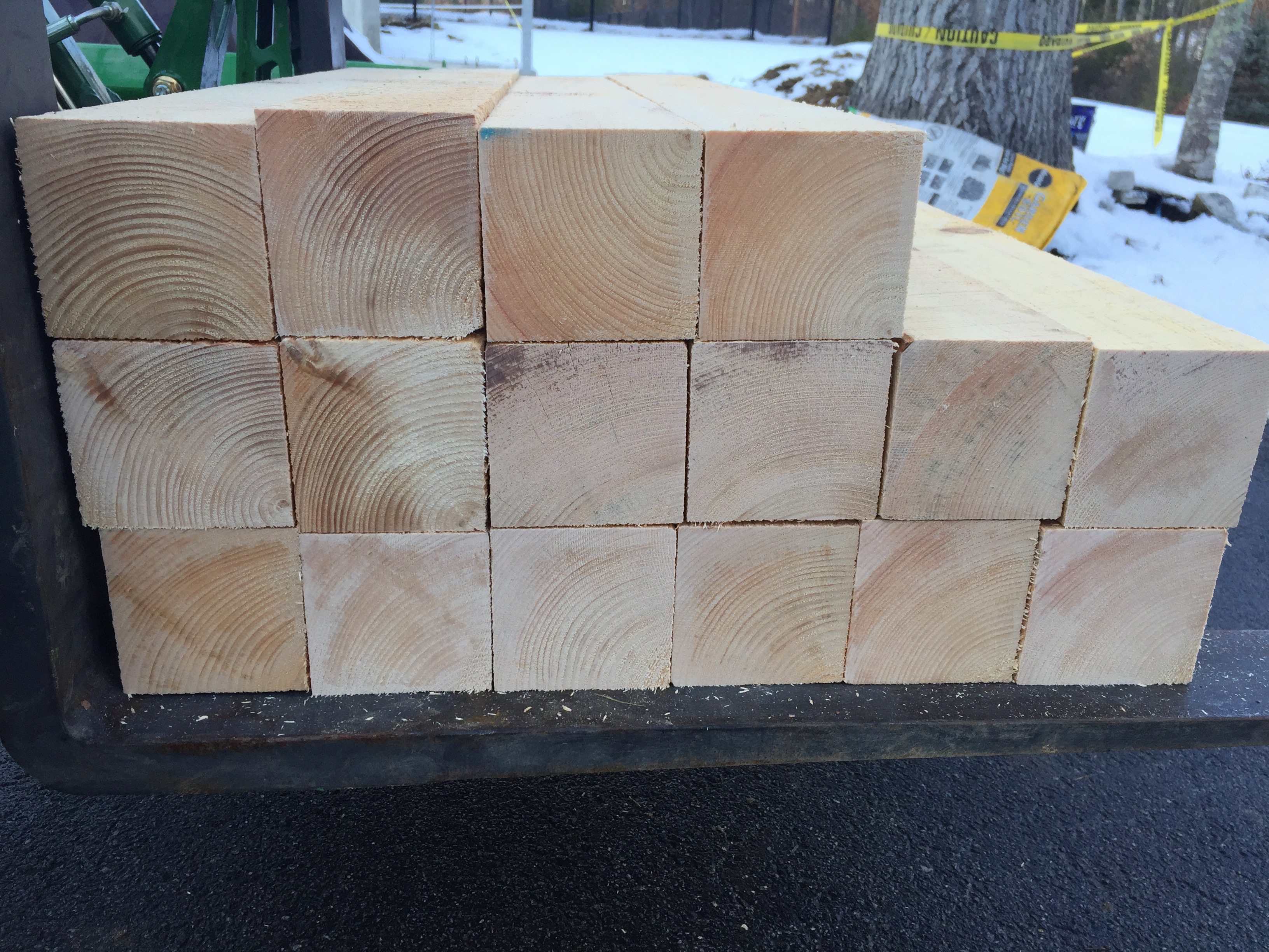
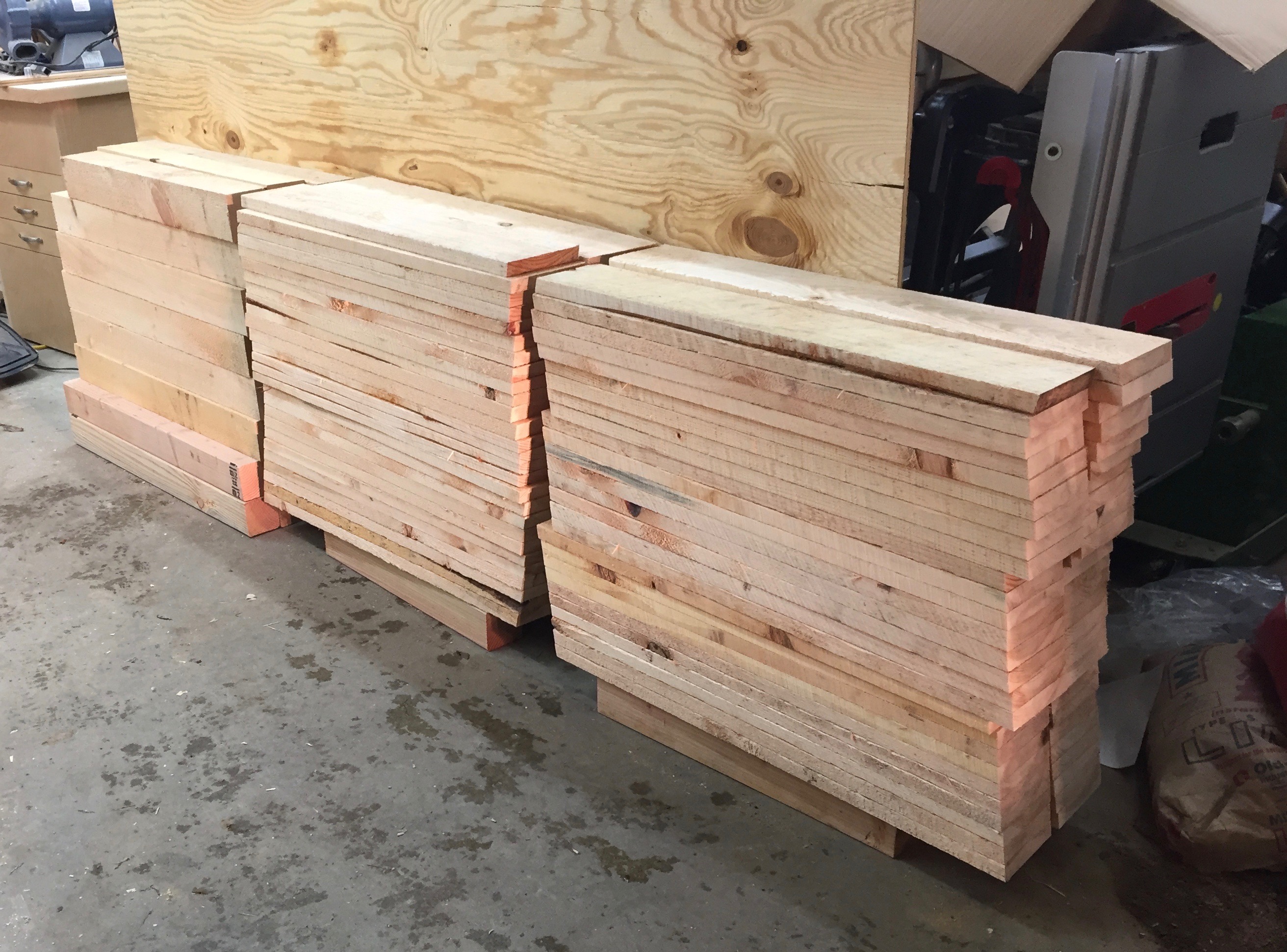
Stacks of cut legs and beams back in the shop
I then brought my wood into the heated shop as we were getting some snow and stacked them as you see above. This was a big mistake as I’ll describe later. I planned to be out there the next day but with snow and a baby in the house they sat out there for a week. If you bring sopping wet/green wood into a heated shop, make sure you sticker them so air can flow around all the edges and the wood can dry evenly.
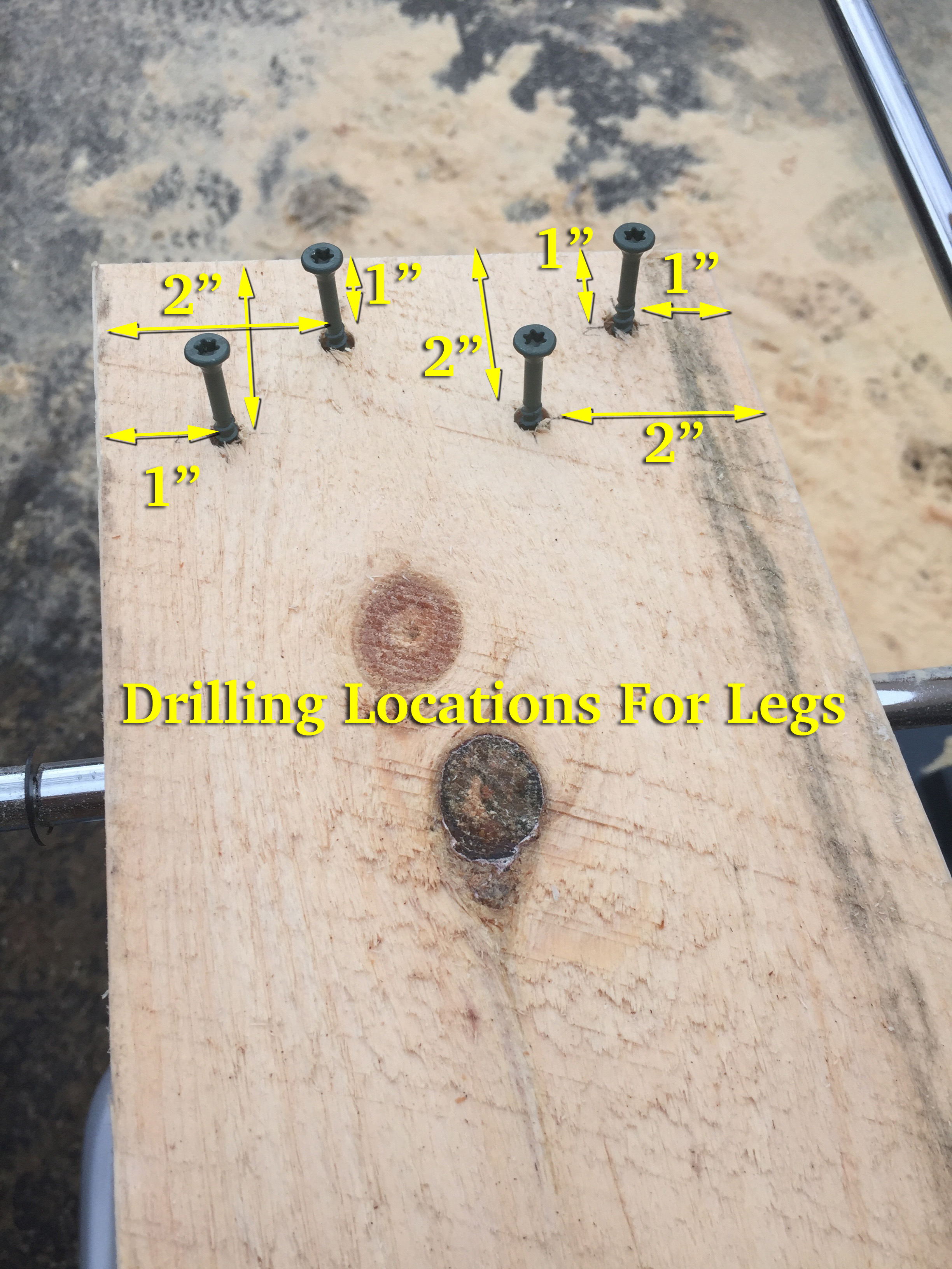
Layout for the 2″ ceramic star drive deck screws.
With all the legs cut I started to layout for the screws. I grab two combination squares and set one to be 1″ and set the other to 2″. This allows for fast/efficient layout. (see above image). Each of the screws is either 1″ or 2″ from the edge or top of the board. The screws are staggered to help avoid splitting the wood. I used DeckMate 2″ ceramic coated deck screws that have a nice thick shaft and are rated for outdoor structural use and do not rust. Do NOT use drywall screws on this sort of project, they are far too weak and not meant for the outdoors. One 5lb box of #8 2″ screws was enough to attach all the legs. After layout I pre-drill each of the holes and start the screws into the boards — this makes it a lot easier to assemble the horse later on.
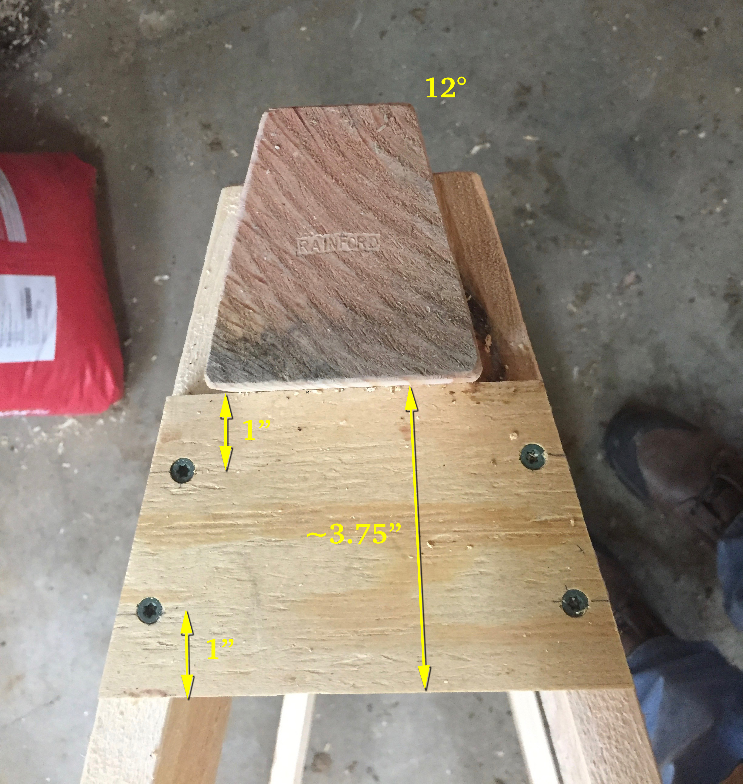
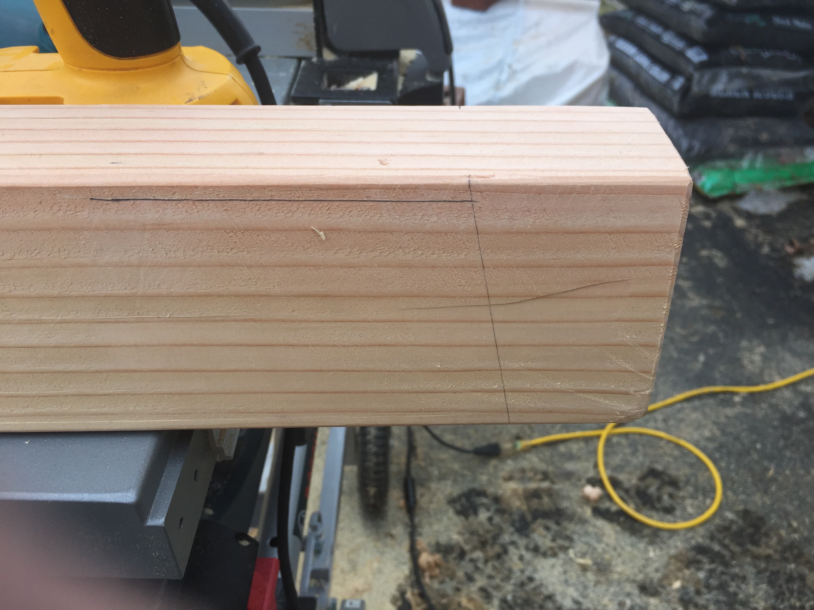
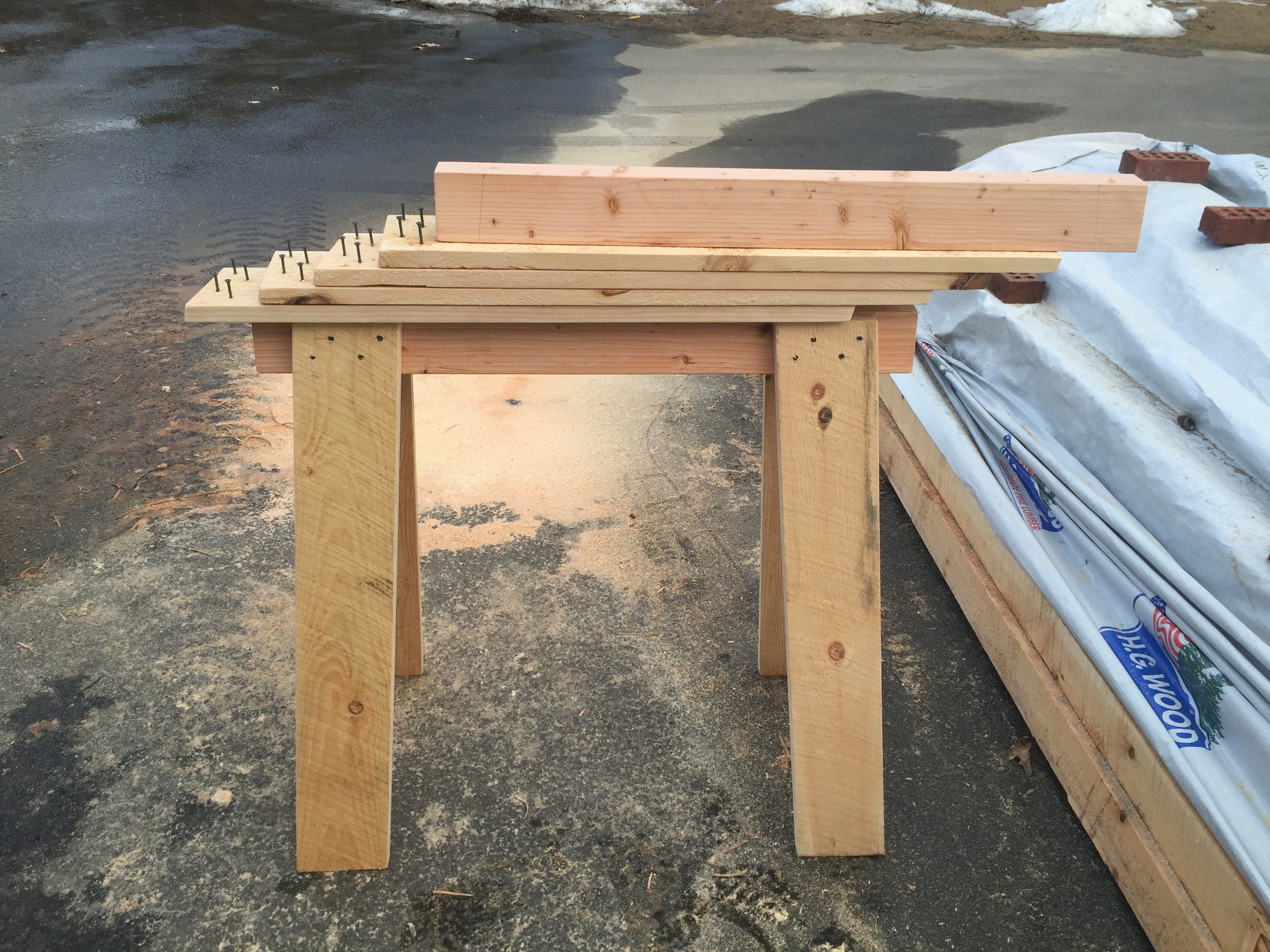
Laying out the beam. 5 degree angle is set in 2.5″ from the end. The top of the legs should be 1/4″ below the top of the beam.
For the beams I make a tick mark 2.5″ in from each end on the top edge of the beam. Using a protractor I make a 5 degree line down the side of the beam — this splays the legs and gives use nice stable horse. Having two protractors on hand is nice as I have one set for the right and one set for the left. I then set a combination square to 1/4″ and make a line along the top edge of the beam — this allows me to line up the legs during assembly. I also broke all the edges with a block plane.
Another horse ready to be assembled
Early on I made a few pairs of saw horses to work from and did the majority of the horses as a large run.
Attaching the legs — I added one leg at a time, usually only sinking 2 or 3 of the pre-started screws into the beam. I add one leg, then add the second leg on the same side of the beam. This makes it easier to stand the horse on those two legs and add the third leg. When adding the 4th leg you’ll want to make sure all 4 legs are properly resting on the ground. If your horse wobbles this is your chance to adjust the legs. When the horse is standing the way you want you can sink the rest of the screws on the legs. When using an impact gun you don’t want to sink the screws any further into the wood than you absolutely have to. Ideally the screw heads should come to rest in the same plane as the surface of the wood, but green pine can be a bit soft so some of them may go deeper before they have enough grip to pull the leg tight to the beam.
Mass producing gusset plates.
With a beam and set of legs ready to go and standing nicely you can take a plywood gusset blank, bring it over to the partially assembled horse and trace where it meets the legs. Ideally the gussets should not stick out farther than the legs, otherwise they might catch on things. Making them say 1/32″ inside of the surface of the legs is what I shoot for. Using that traced piece I cut it and label it as a the template and use that for laying out each of the subsequent gussets
Important Notes About Gussets:
1.) When cutting the gusset the beveled end is always ‘up’ on the installed gusset — it mates nicely to the underside of the beam.
2.) When installing a gusset make sure the 5 degree bevel is facing the correct way so that it rest tightly up against the beam.
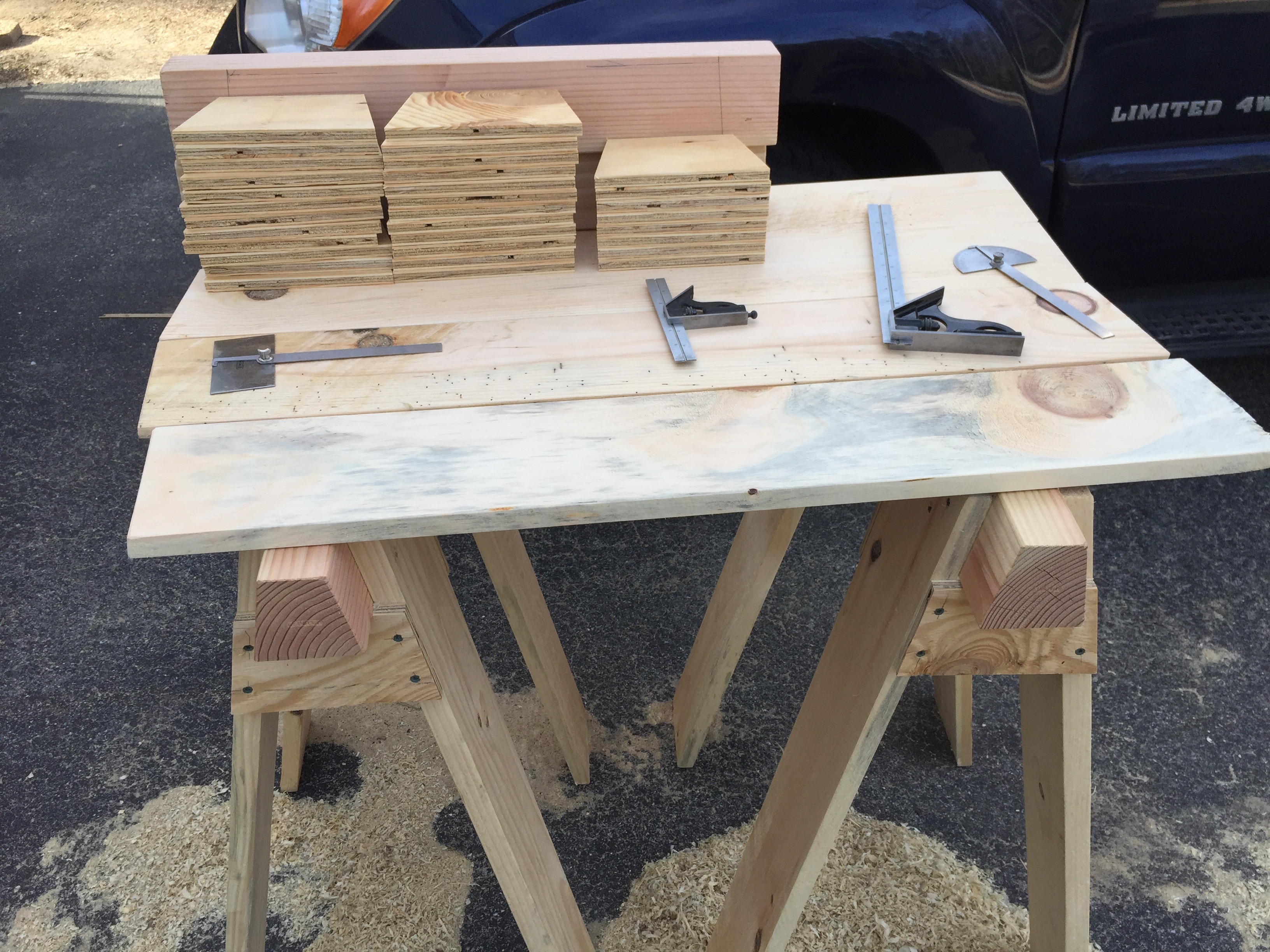
Impromptu work table
With a few horses pressed into early service I was able to make a makeshift table that allowed me to layout/mark all the of the gussets. Each one is secured with 4 screws. I made a mark for each screw to be 1″ down from the top or the bottom of the gusset and centered on the thickness of the leg, so for most that would be ~3/8″ in from the mitered edge. I turn a horse on its side and place the marked gusset where it is going to go. I then pre-drill the gusset in place and drive the screws. I used #8 1-5/8″ Deckmate Ceramic Star-drive screws and again a 5lb box was enough for this project.
Each horse required 16 2″ screws and 16 1-5/8″ screws.
Saw horse with dimensions.
And now we have a completed horse! The image above has some more dimensional information for quick reference.
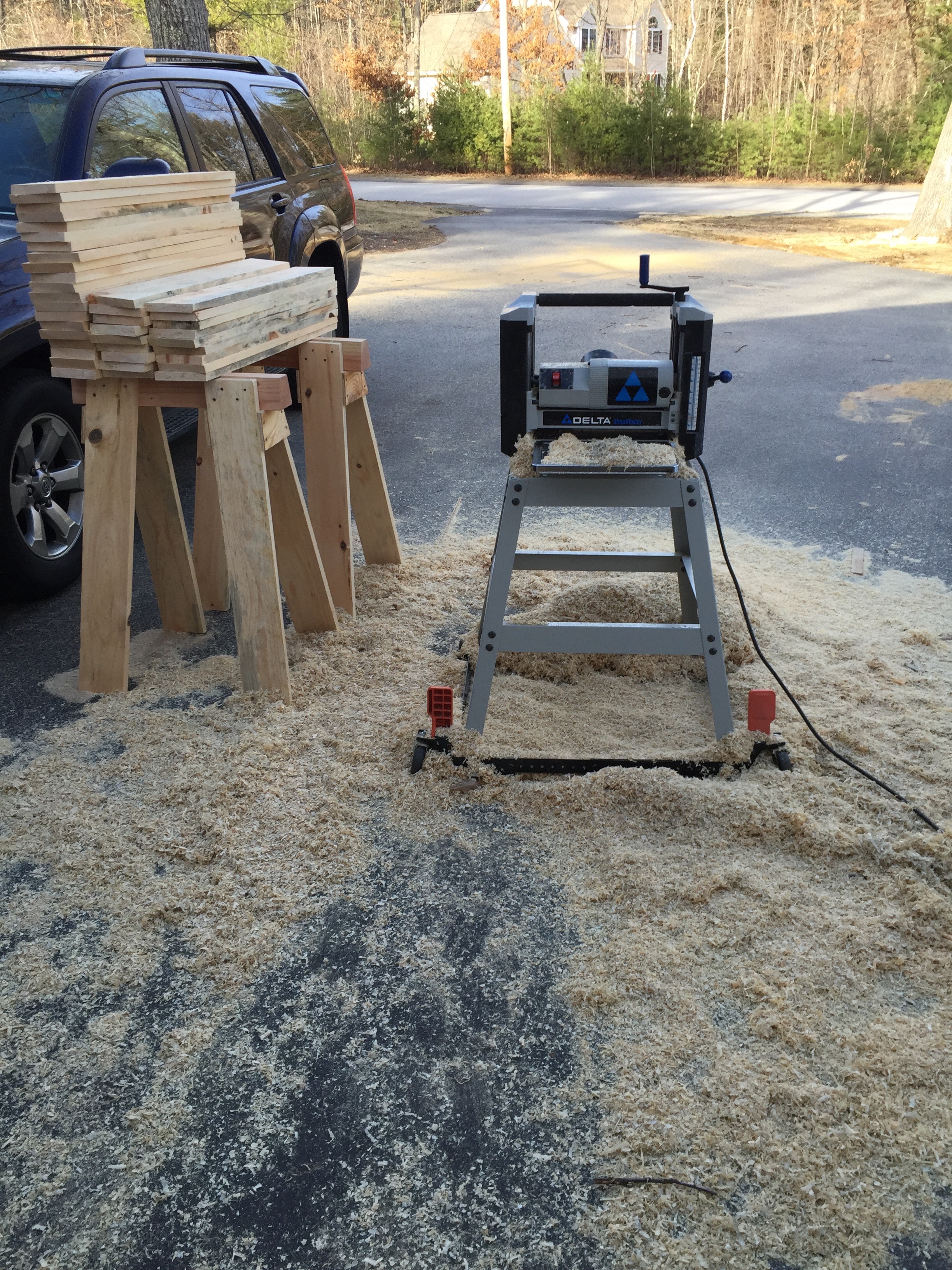
Lunchbox planer getting a workout
Now back to that mistake I mentioned earlier. By leaving the cut wet boards tightly stacked a mold/fungus quickly bloomed on half of the boards. I have a lot of allergies so I didn’t want to handle those boards any more than I’d have to, and it was unsightly, so I suited up and with my dust mask and fed them through my lunchbox planer. I also didn’t use my dust collector as I don’t want that wet fungus living in my filter. I planed the rough boards smooth and stickered them up to dry in the sun as I worked on other horses.
Letting the legs air dry a bit
That little mistake accidentally created ‘Denim Pine’ — pine boards with a blue tint that results from that fungus blooming and is desirable to some folks, presumably non-workers that like the look of it. (See above and below). With the mold/spores/fungus/grossness removed and stickered the legs will dry and be fine to use. As I completed each horse it will live out side where it can dry at a steady rate until the barn gets finished.
Some ‘Denim Pine’ Legs
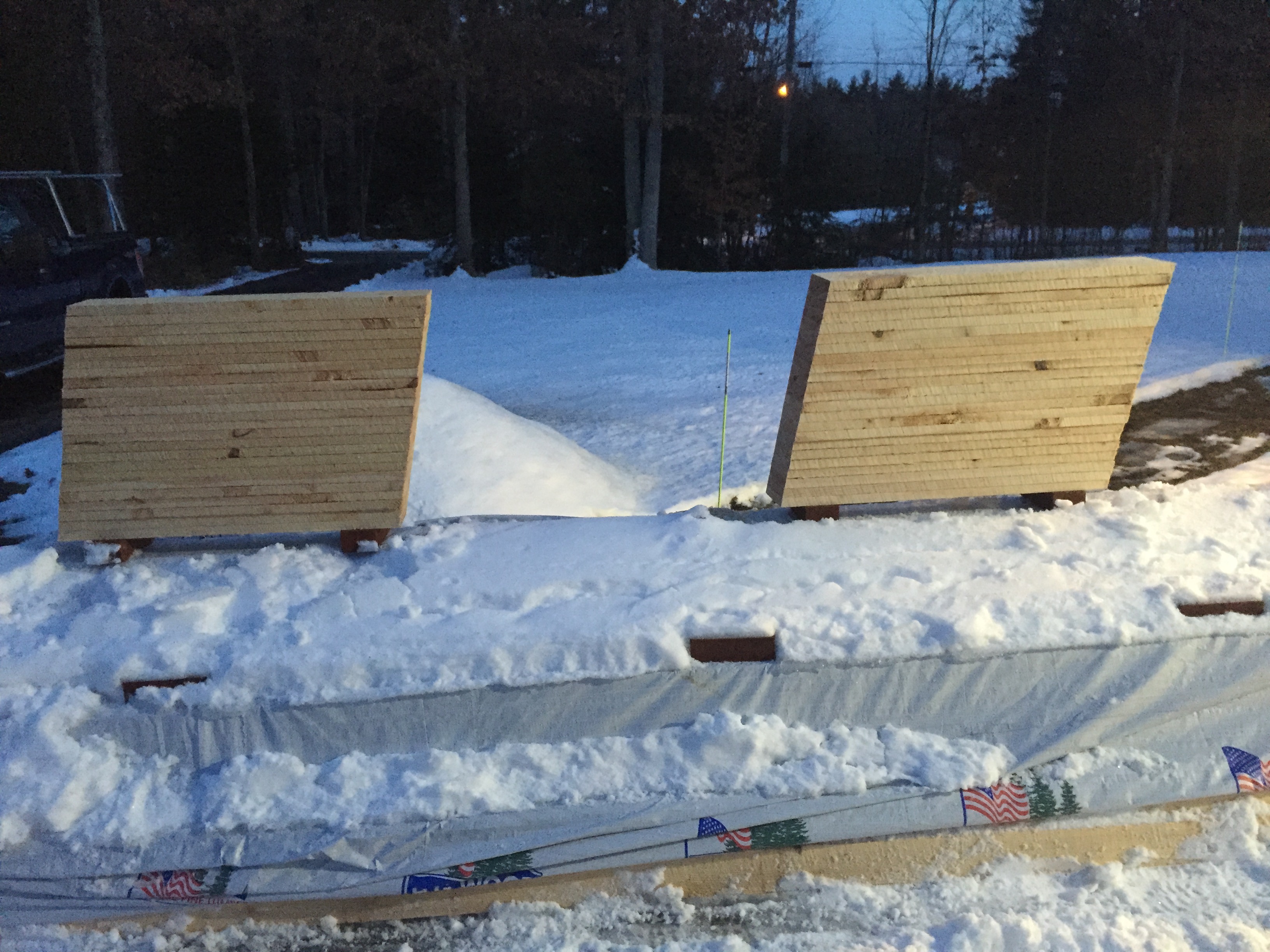
How do you store all of these horses?
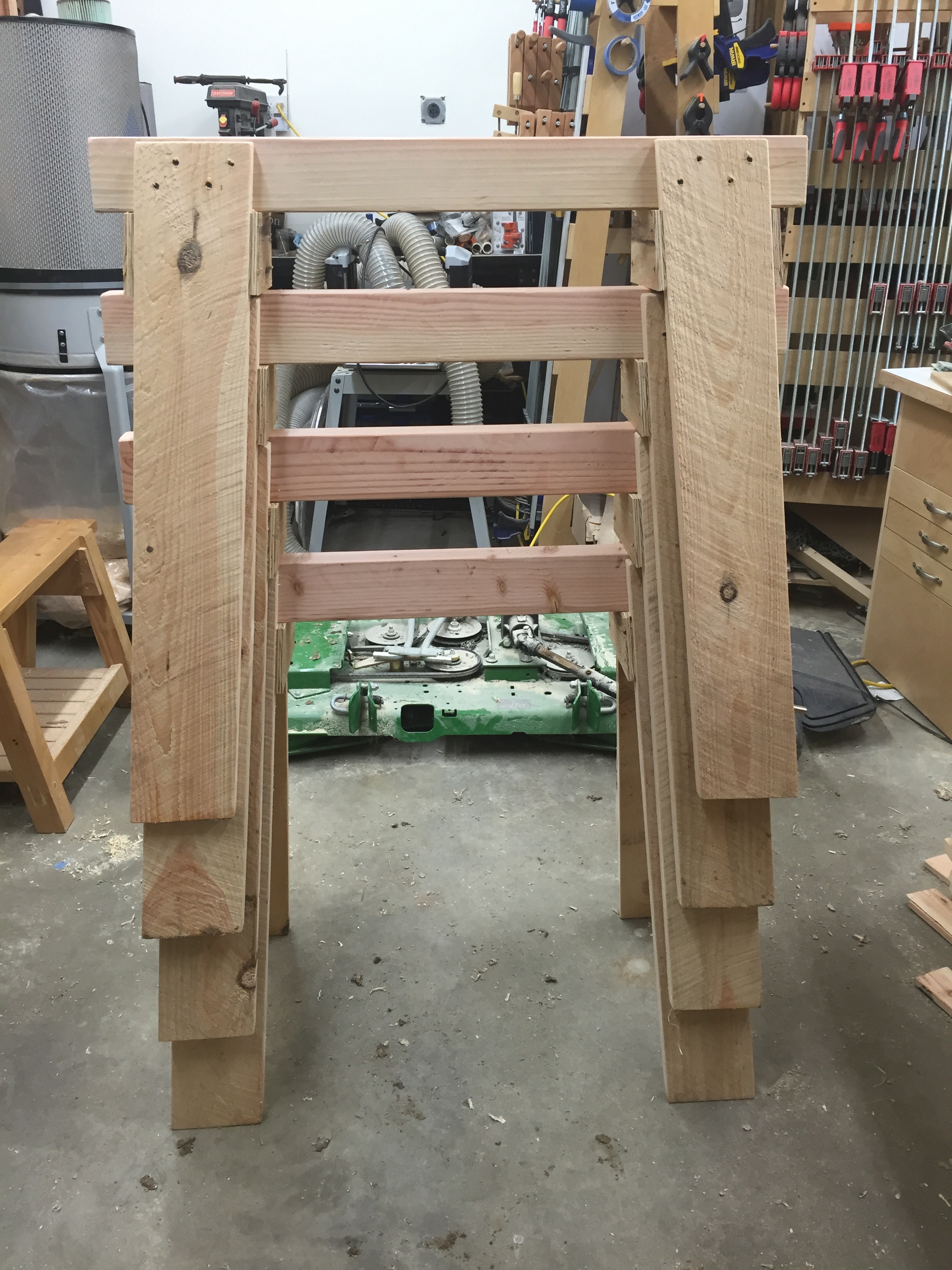
Stacked horses.
The horses stack nicely and even when stacked all the wood can dry nicely.
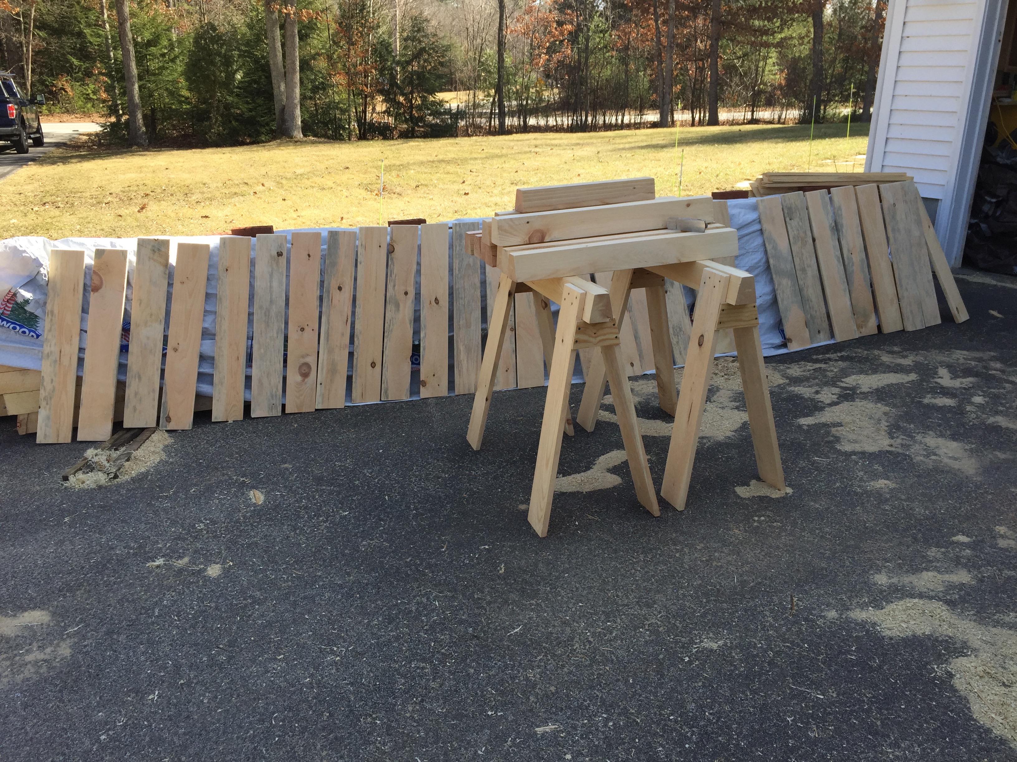
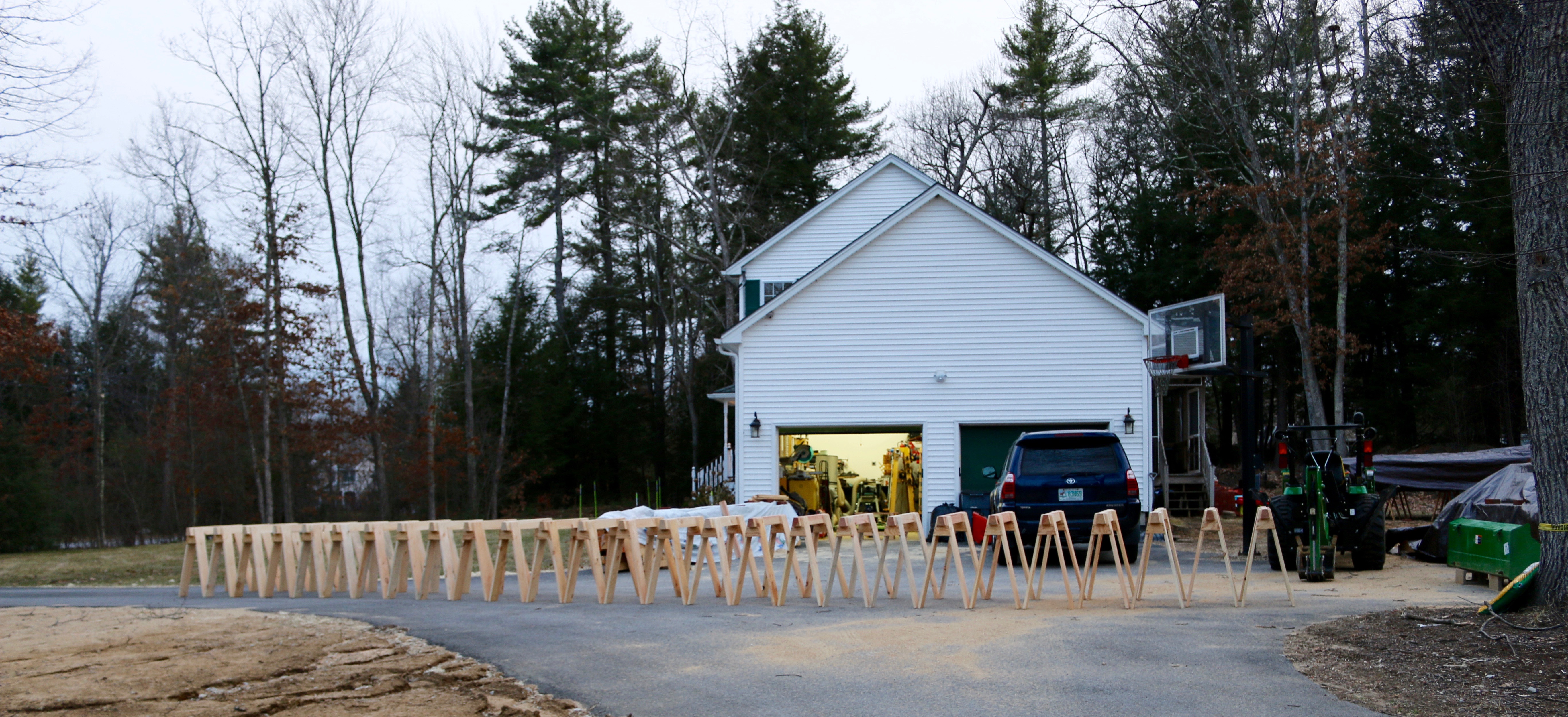
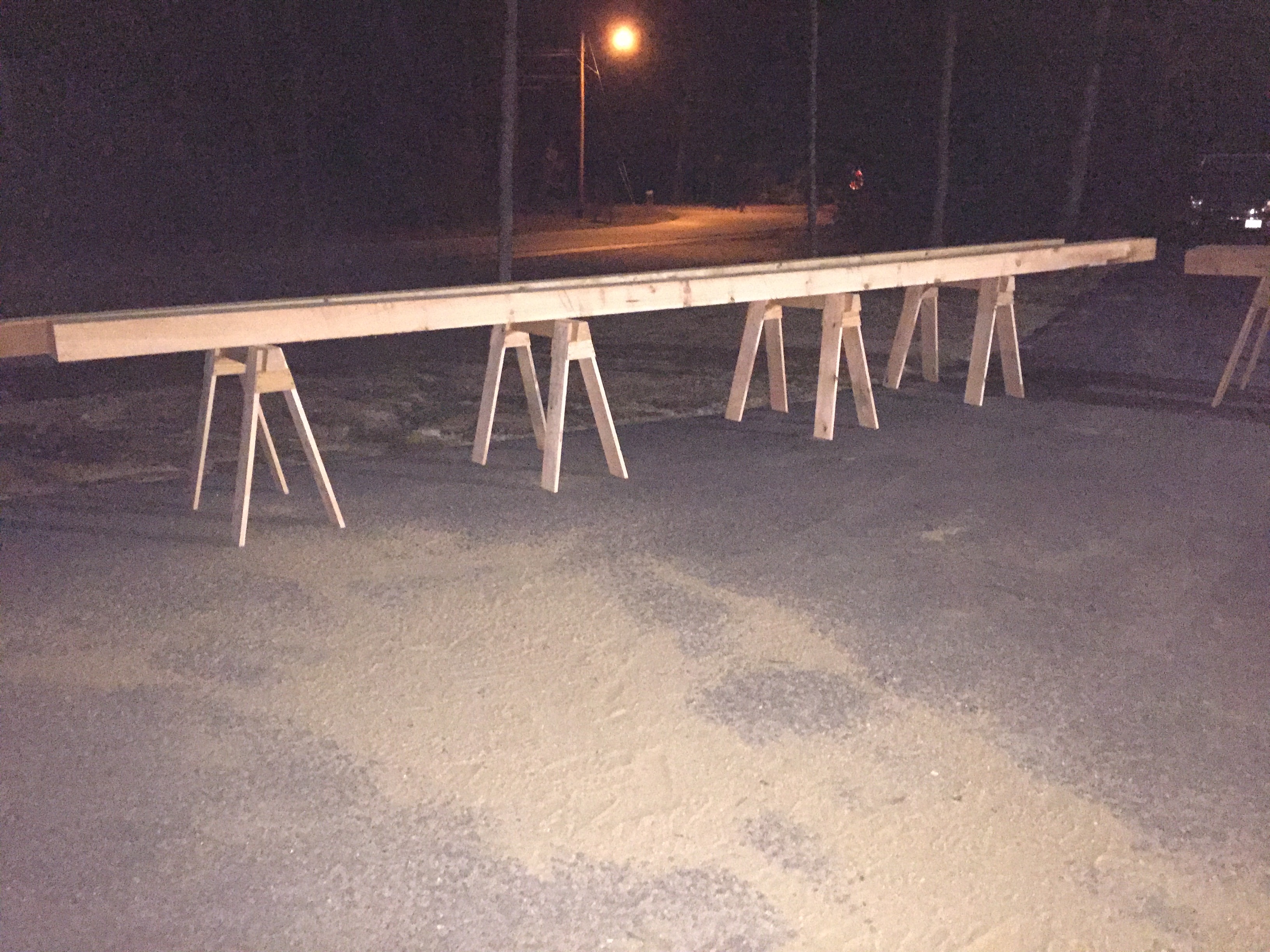
Wide angle view of the horses
This was the largest run of horses I’ve made to date so I set them all up out in the driveway just to see them all in one place.
2 ponies in the foreground 26 horses in the background
Two of the horses, my ponies, had a 24″ beam as two of the 4x4s were a little short and I thought it would be nice to have a set that can fit into a tight place.
It looks like a TON of horses, but these 12, plus the 12 I already had will just barely be enough for the barn build.
What do you plan to do with all these horses?
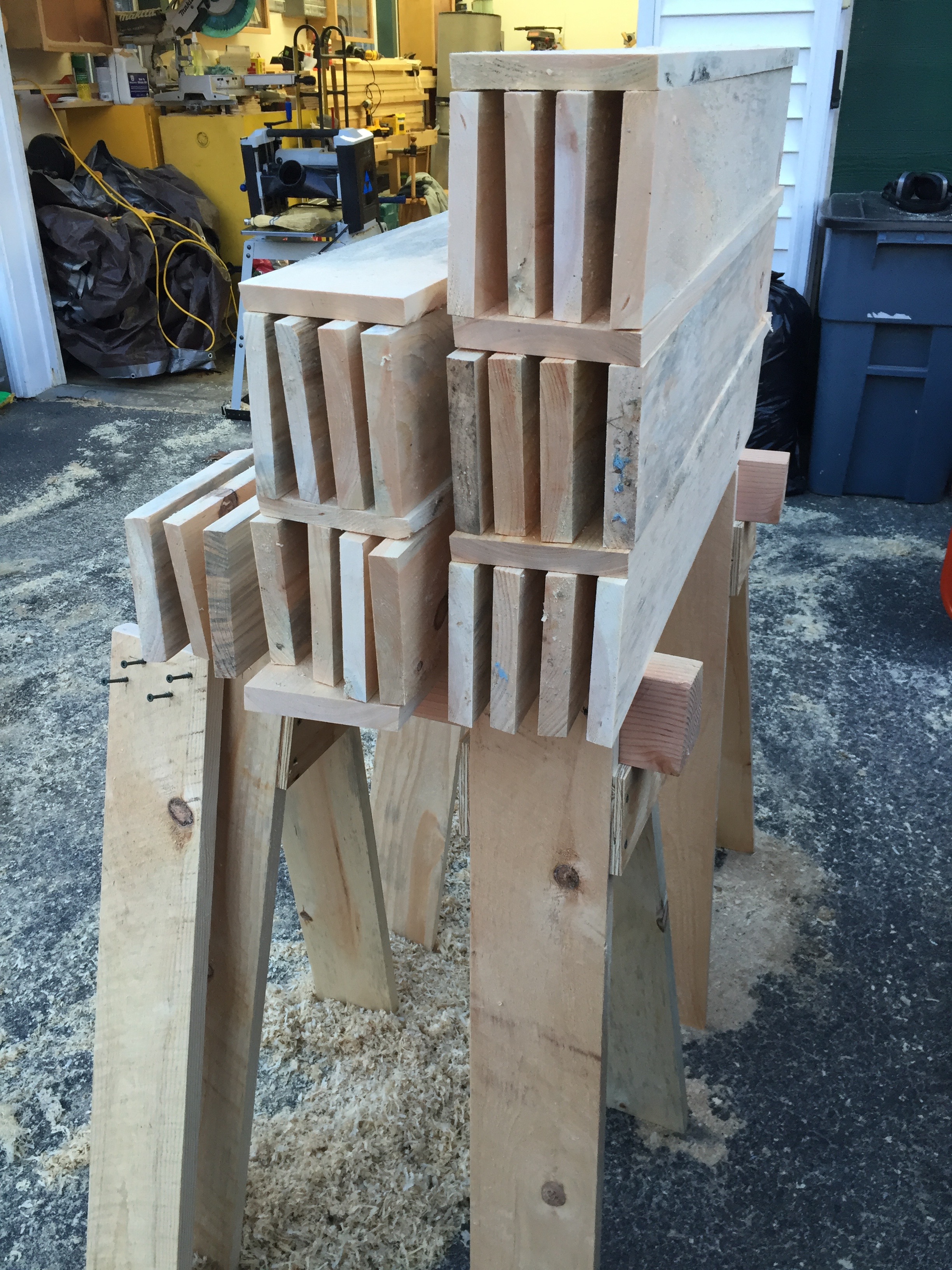
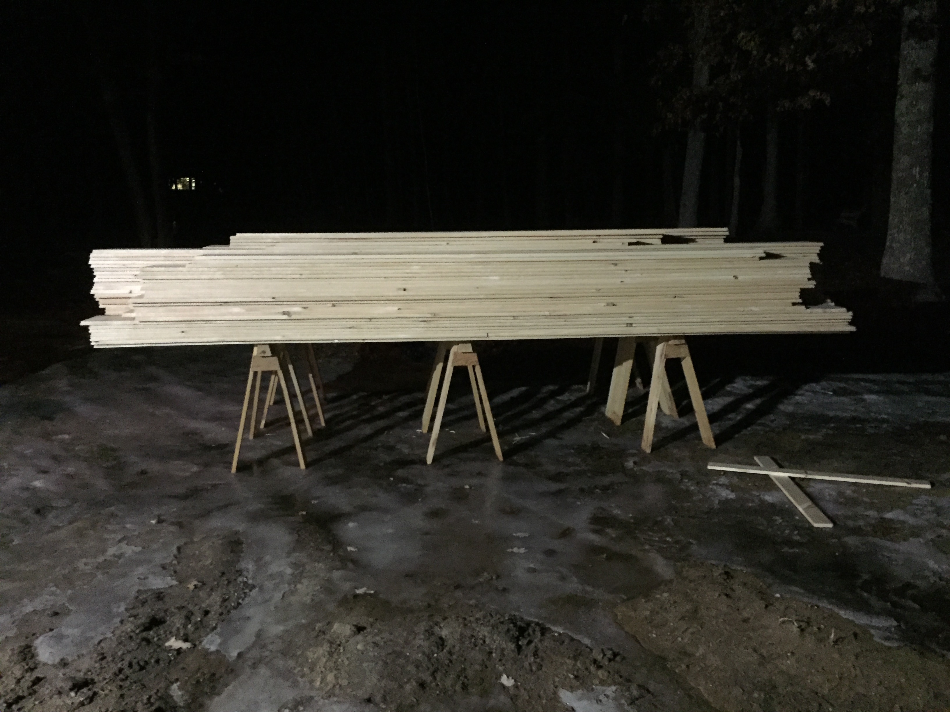
A LOT of shiplap siding on horses. 10-12″ wide 16′ long pieces
Above and below you can see a couple thousand linear feet of 16′ shiplapped pine sheathing held with ease by these horses.
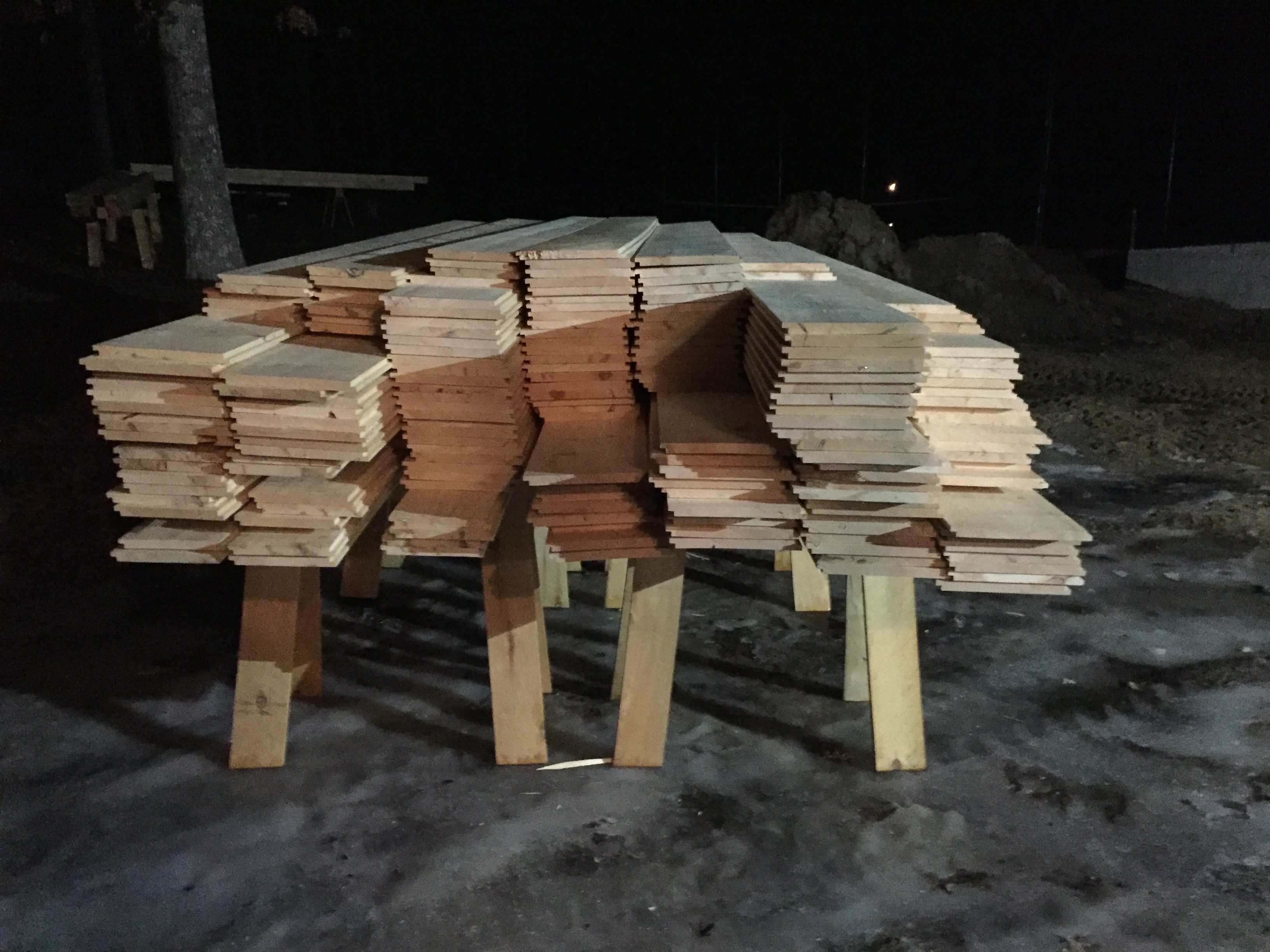
A LOT of shiplap siding on horses
In the photo below are 24 2″ thick 12″ wide green pine planks that will be used in the barn loft. I estimated this wood to weigh 1800lbs and the 4 horses below seem to hold it with ease.
4 horses holding over 1850+lbs of green pine planking
And below are some 6×9 25′ long timbers.
Horses holding 6″x9″x25′ timbers
As you can see these versatile horses are at home in the shop or out on a worksite and I hope that you’ll build a few pairs for yourself. If you do, please let me know in the comments.
Building a window sash by hand can sound intimidating, but with some practice it can be an enjoyable experience. Early window sash were built by hand designed to be maintainable — if a component broke or rotted out it could be replaced — something that is not possible with most aluminum and vinyl windows you see on the market today.
Continuing Education Department at the North Bennet Street School, Boston, MA
A few weekends ago I taught a two day workshop I developed on building a window sash at the North Bennet Street School. This post and the next are a high level recap of the course with some photos from building the prototype in my workshop and what we did in the classroom
Nice quarter-sawn stock for muntins.
Stock selection is important. My wood of choice is Eastern White Pine, preferably quarter-sawn heart pine which is easy to work, weathers well and historically appropriate in my area — the greater Boston area.
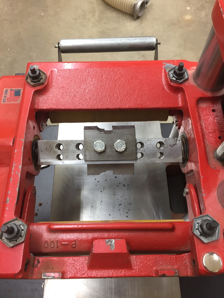
Sticking Knife Profile in the Williams and Hussey
A profile can be run by hand using sash planes or using a router table. For larger runs a custom molding knife can make fast work of this often tedious task using a machine like the ‘Williams and Hussey’ molder. (Shown above and below)
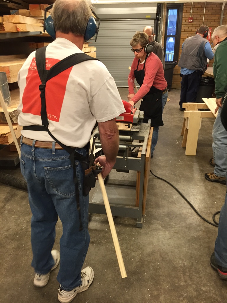
Profiling the stock
We make a few passes to get near the finished size wanted and then a final cleanup pass at the end to leave the piece with a nice finish.
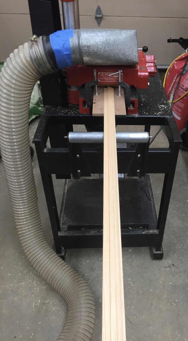
Profiled stock coming out of the molding machine
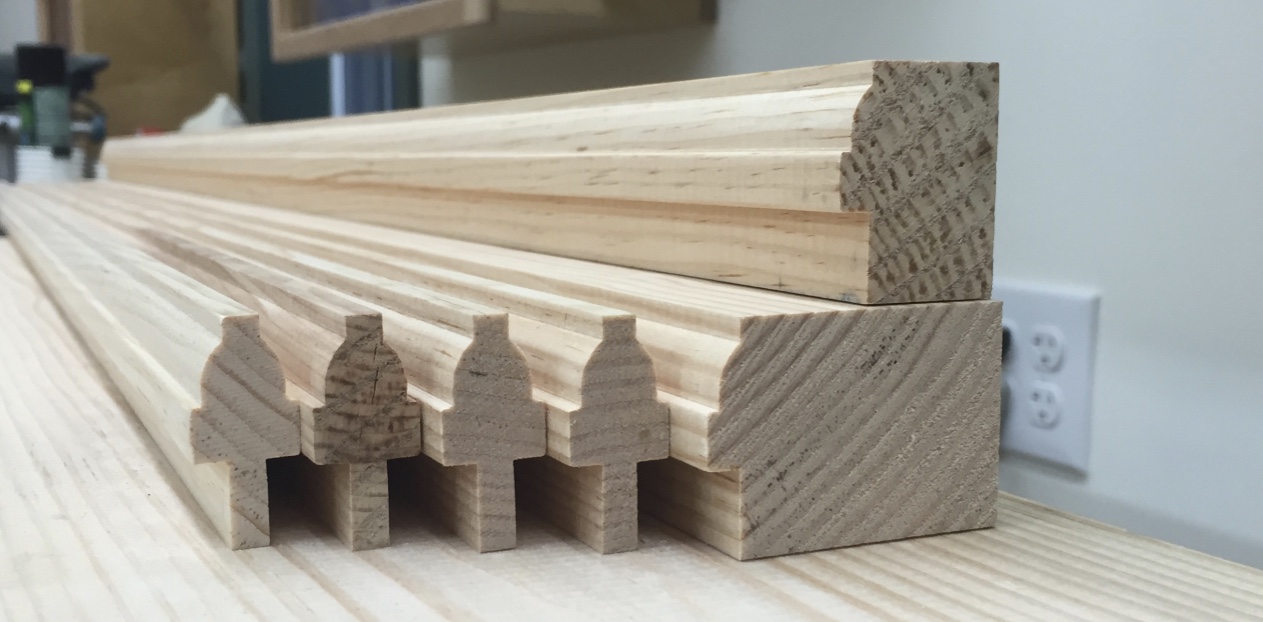
Rails, stiles and muntin stock are run using the same setup on the machine — this way all the profiles are consistent.
Rails, stiles and muntin stock profiled.
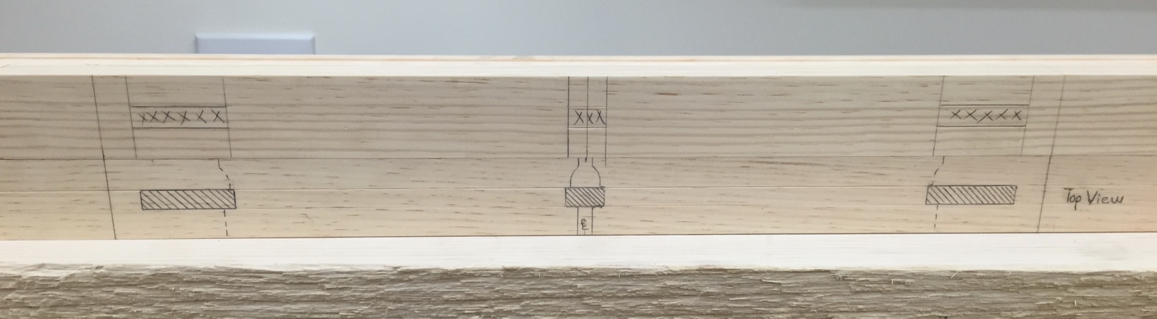
Next up is the use of a story stick — this traditional device is effectively a set of plans laid out on a piece of stock that matches the rest of your milled stock. Key locations like mortises are transferred to the work piece by using a marking knife and a combination square. The knife allows for accurate and consistent transfer of measurements to the work-piece.
Using the story stick to transfer measurements to the work piece
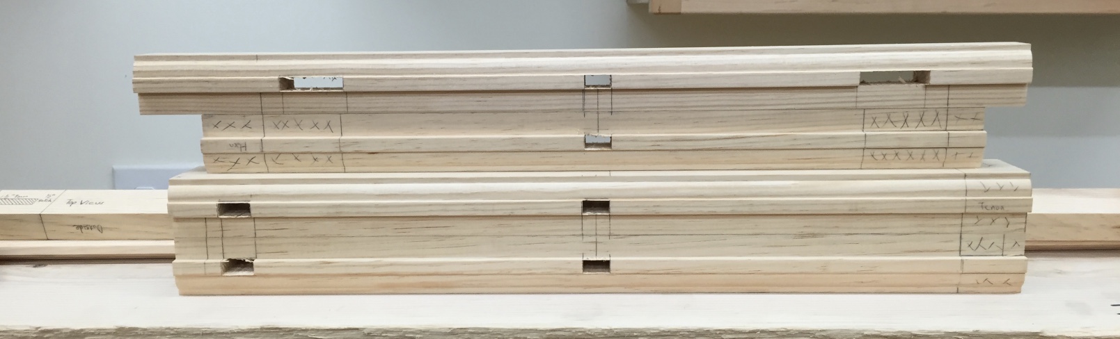
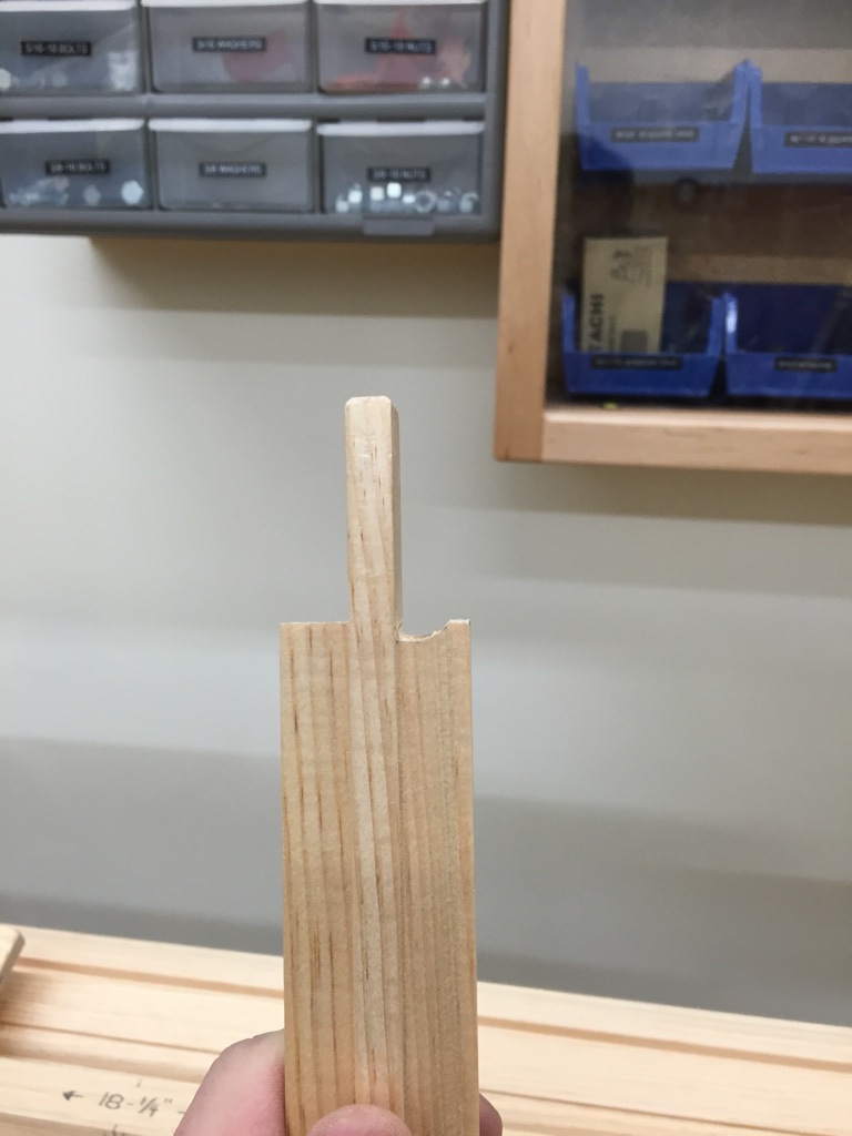
Shown below are mortises cut either with a hollow chisel mortiser or by hand with a mortising chisel. Also note that the work pieces are deliberately left long. These ‘horns’ allow for more relish to support mortise walls from blowing out and also allow the sash to sit in the shop and not ding or damage the piece as it is worked on and eventually glazed.
Mortises cut
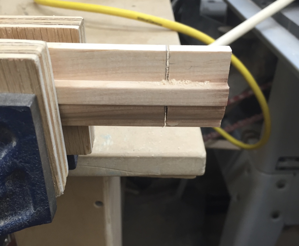
Once the mortises are cleaned up its on to cutting the tenons. Once the piece is laid out I start by cross-cutting the shoulders. (See below). I then use a chisel to pop off the waste or for larger tenons will make a second saw cut (This time ripping down to the shoulder cut) and clean it up with a chisel.
Cutting in to reveal the tenon
With the shoulders in place I can dry fit them (using the square shoulders that are on the exterior side of the sash) to make sure I have a tight fit as seen below. Note that I am not fitting the tenon yet, just the shoulder to start.
Test fit the central muntin
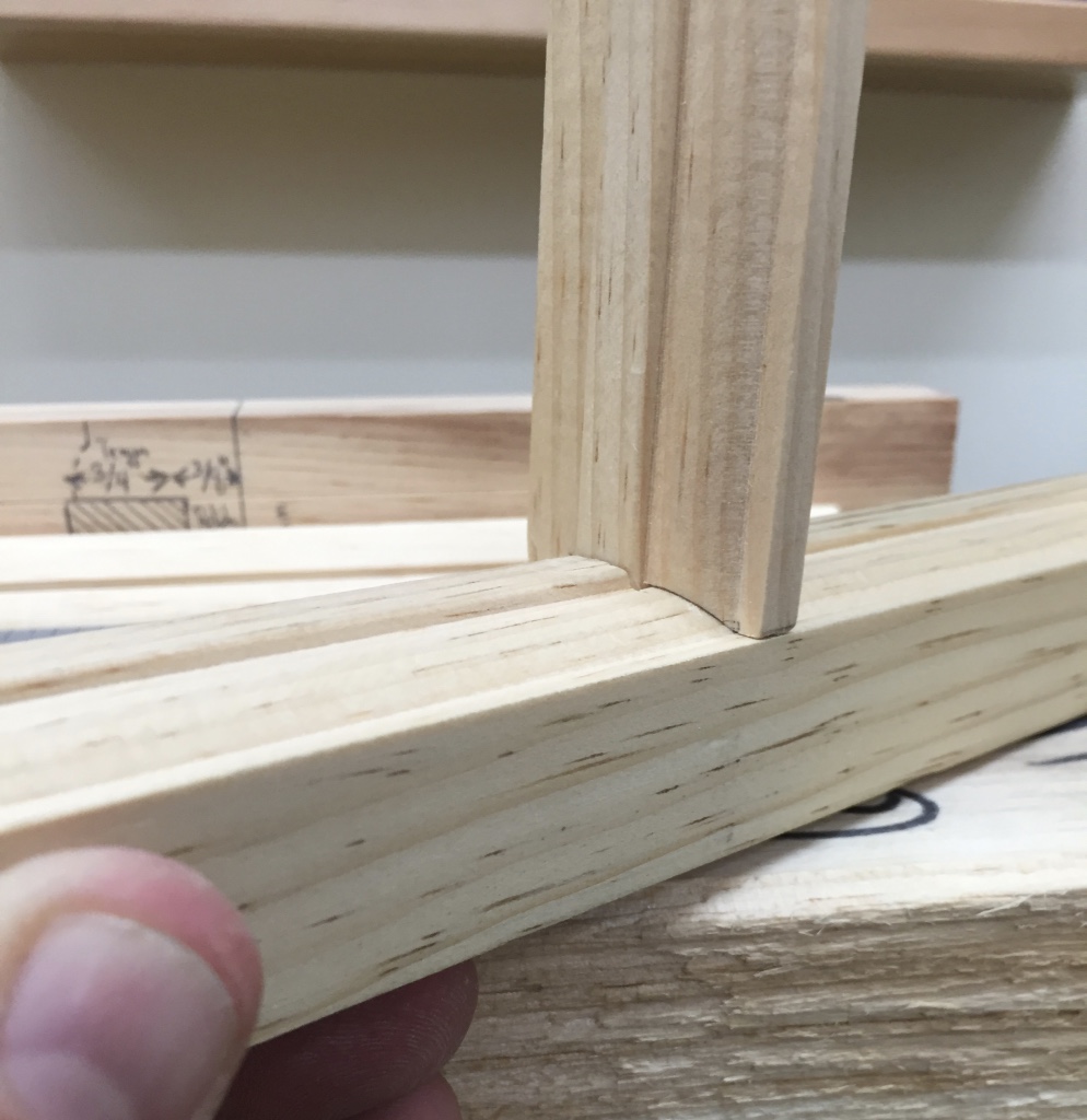
Next up was the coping. I make use of a saddle block with a 45 degree ramp and some in-cannel chisels to cope the muntin stock as shown below. With the cope in place I can now test the fit of each of the tenons into its mortise.
Tenon complete and profile coped
This creates a nice tight joint that allows the pieces to mate together in a pleasing manner that allows to profile to make that 90 degree transition from the horizontal to the vertical.
A nicely coped joint
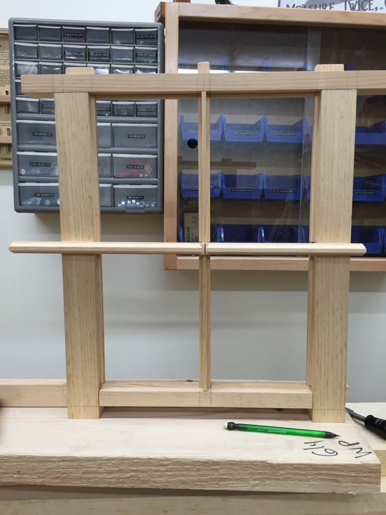
I use a similar process for fitting the horizontal muntins — starting first with the center joint as this can be fussy at times. I want each horizontal muntin to meet cleanly in the center and have both tenons fill as much of the mortise as possible. I leave the stock long so if something goes wrong with the joint I can cut off that inch or so and try again without wasting a whole piece of stock. With the center joint in place I’ll cut the other shoulder and fit it as we did with the vertical muntin and then cope the joint and test those tenons.
Test fitting the shoulders for the horizontal muntins
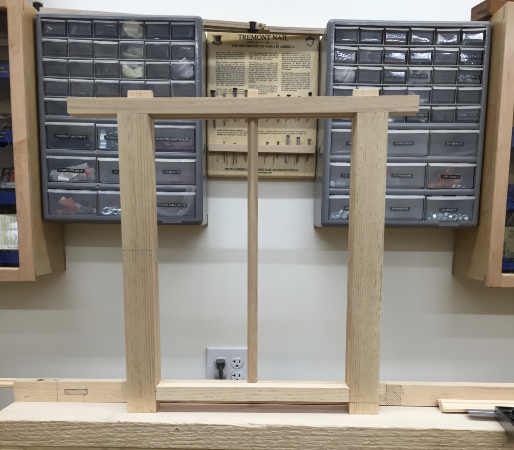
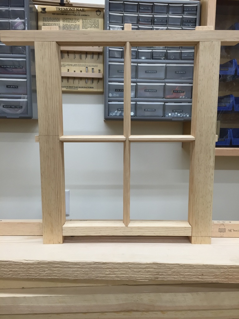
With all the primary joinery completed its time to dry fit it all together and check for square. All the joints should fit together well and the shoulders and copes should be nice and tight.
Test fitting the primary joinery. Note the horns will remain until we paint the sash.
If your joints close up with some mild pressure don’t worry too much as the draw bored pins will help pull the joints together and keep them closed. With each stage in this process the sash becomes more and more rigid.
In the next post we’ll talk about making pins, draw-boring, cutting glass and glazing.
Every family has its own unique holiday traditions. For my wife and I we seem to spend Thanksgiving replacing door hardware and adjusting doors. We did this several years ago in our condo when we lived in Kirkland, WA and again in our home here in New Hampshire. Both times I was swapping out builder grade brass Schlage hardware for nicer Schlage ‘Georgian’ style knobs and hinges with a satin nickel finish.
We’re lucky in that our house is from 1999 and has had a minimal amount of settling — especially compared to the 1910 Craftsman Bungalow we used to rent wherein virtually no door closed properly until I spent a Thanksgiving break adjusting all those doors as well.
With all that door tweaking I’ve refined my method for adjusting the doors and wanted to share a few tips on how I tune up a sagging door.
Evaluate the door:
* Does it close? (and stay closed)
* Do you feel the door rub against the jamb at all? (Are there visible wear marks from rubbing?)
* Is the hardware securely fastened? (Any stripped out or cammed out screws? Lift the door handle a bit and see how the hinges react — do you see slop in their movement? Are some of the screws loose?)
* Has the door been modified? (Anything removed to make room for a crooked or settled door frame? Has the hardware been modified?)
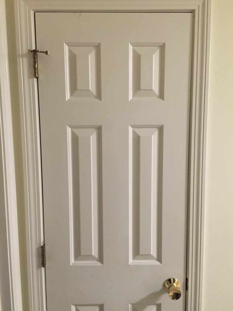
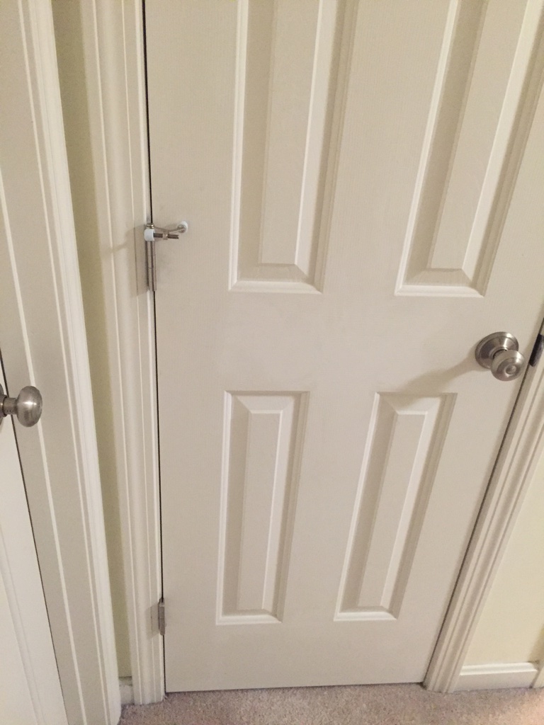
BEFORE: Existing door with brass hardware sagging
The above door is door to my upstairs hall closet. It rubs a little bit when you open or close it. Let’s take a look and see why.
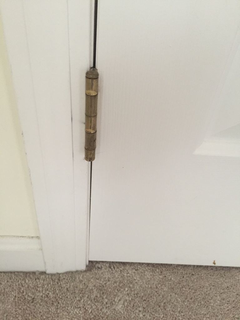
Example of lower left side of door rubbing as door sagged.
Looking at the lower left side of the door I can see the door is pressing against the jamb. At the bottom you can see the spacing between the door and the frame tapers off into the place where they are touching.
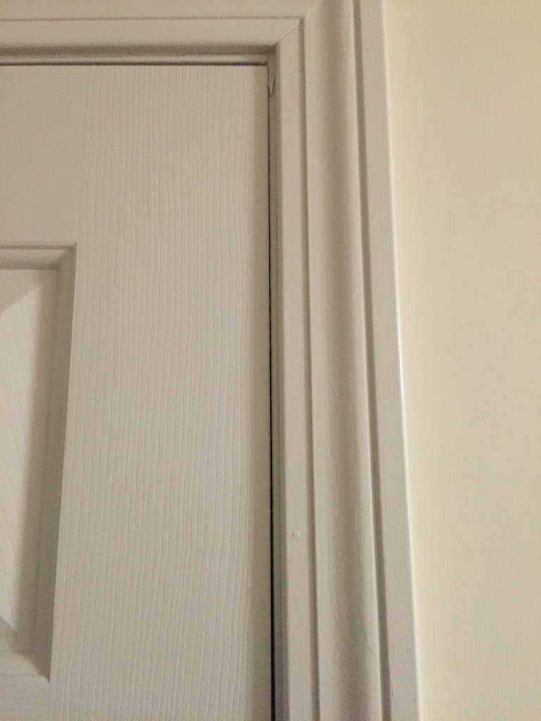
Top right of door rubbing against the frame.
As is no real surprise if we look at the top right of the door we can see where the door is touching and rubbing on the right jamb. If I pull up on the door handle I can see the door go back into the position it should be — looks like the top most hinge is a little loose.
How do we fix this problem?
In my case I want to examine the doors as they were and also swap out the hardware so anything brass is a ‘before’ photo and anything nickel is an ‘after’ photo.
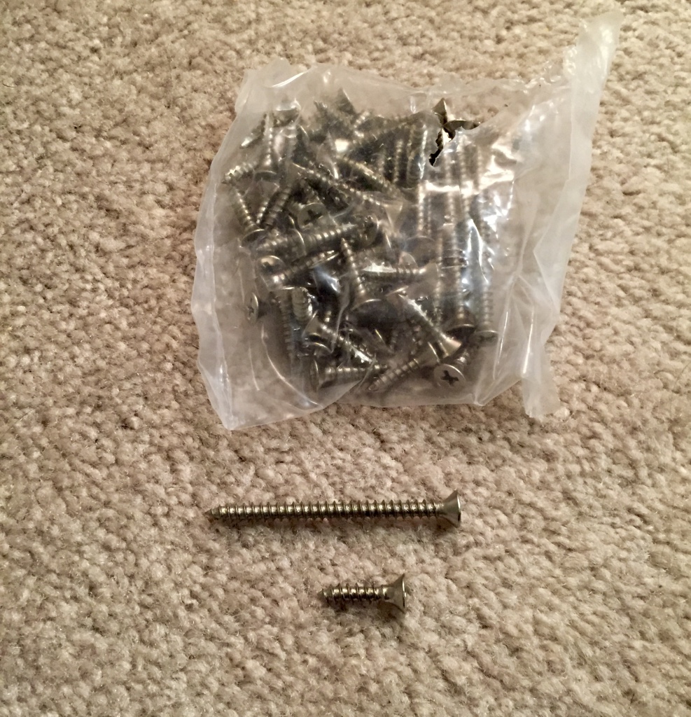
The first thing I like to do is make sure the screws holding the hinges in place are nice and tight. The default screw most hinges come with are short ~3/4″ screws. After years of use or abuse (say something heavy like a shoe tree hanging from the inside of a door) the screws can come loose and/or strip the wood that once held them securely.
Brushed nickel screws. Better hinge sets will include some longer screws that are helpful in correcting/preventing door sag when used.
Better hinge sets will often include some longer screws — usually enough for 1 long screw in each hinge. I’ll start by installing 2 screws — one each in the top and bottom of each leaf. As I screw them in firmly — and by hand — I can feel how well the screw is gripping into the wood of the jamb and the wood of the door. If any of the screws just keep spinning then the screw has been stripped out and is now a candidate for one of the longer screws. If the screws are holding then I will use the longer screw in the center hole on the hinge leaf that is on the jamb. This longer screw should go through the jamb and into the heavier framing and provide a strong and longer lasting connection. If the center screw hole was sound but one of the others was stripped out I will put the longer screw into that hole.
Pro-Tip: The hinge leaf with three knuckles should be installed on the door jamb and the leaf with two knuckles should be installed on the door itself. (This will provide a better bearing surface for the door’s hinge leaf to ride on and make it easier to remove the door and put it back in the future). If the pin is removable you can drive it out with a transfer punch and install it the opposite way for a door that opens in the opposite direction.
What do to if the long screws won’t grip either?
Sounds like the screw hole has been damaged too much. If you don’t want to replace the door and/or jamb a reasonable fix can be made using a small diameter dowel. You’ll want to drill out a bigger hole, say 1/4″ diameter, through the stripped out screw hole. Then glue and hammer in a small length of 1/4″ dowel to fill the new hole. Allow the glue to dry and cut it flush with the hinge mortise. Then mark the hole using the hinge as a template and re-drill the hole with a bit that is narrower than the screw you are using. Ideally the bit should be the size of the shank (the solid core) of the screw, thus allowing the threads to get a nice grip into sound/solid wood.
Use one of the hinges as a template.
Securely affixing the new hardware fixed the issue on that particular door, but other doors in the house still didn’t line up the way I wanted and/or the hinge was set too deep and needed something more — some shims — to get the door back into proper alignment.
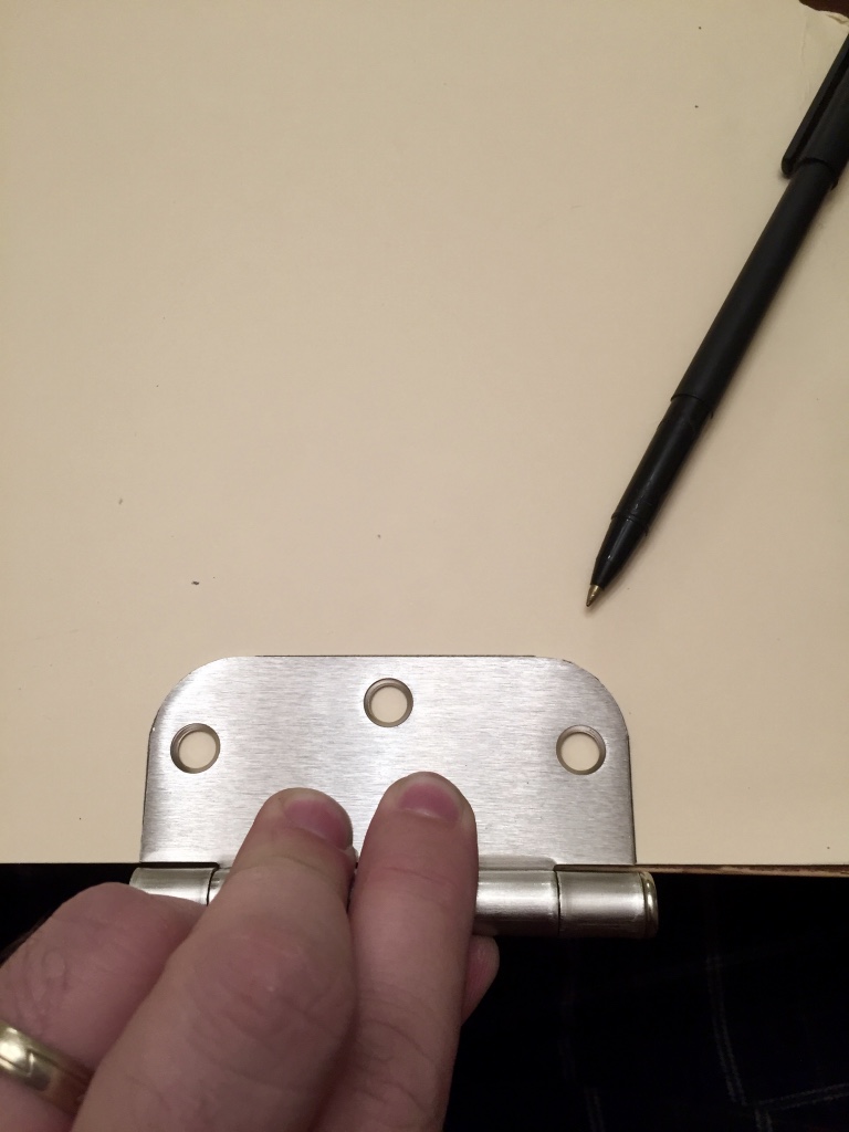
Easy to make shims
I grabbed a manila folder and traced one of the hinge leaves onto the folder. I then cut out what I traced being sure to ‘take the line’ that way I could be sure the template would fit. Also by leaving the folder folded up I could get two shims from each cutting operation. I would test fit the shim and use one as the template for subsequent operations. Also make sure the shim only fills the area where wood would be under the hinge, you don’t want the shims going all the way out to the knuckle of the hinge where they would be visible. Once I had a small stack of these shims I could take a few test fittings and see how many I needed to pad out the hinge so it would be flush with the door jamb or door surface. I would then scotch tape the shims (if I needed to use more than 1) to each other and into the jamb using a small loop of tape. With the shim(s) in place the I’d use the same screw installation procedure described above.
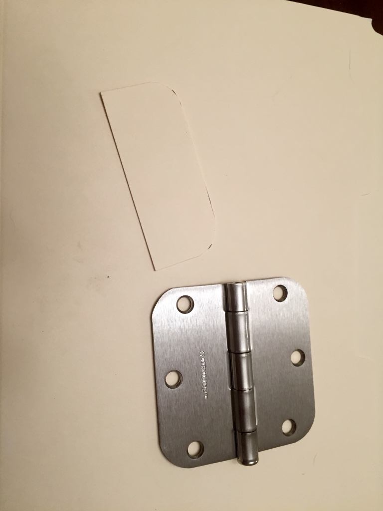
Completed template.
What about the hinge pin door bumper?
A hinge pin door bumper is the little metal bracket with adjustable rubber pads on it used to stop a door from opening too wide and potentially damaging walls or furniture. Once you have your hinges installed you can use a transfer punch (or in a pinch a nail set, nail or another hinge pin) to drive the pin up and out of your hinge. You then put the pin through the bumper and gently tap it back down into the knuckles of the hinge. Once installed you’ll want to adjust the bumper so that the door only opens as far as you want — the bumper may have some spring to it so if you have some heavy handed folks in your house you may want to test it so folks are not over powering the bumper and denting your walls. I put the adjustable side of the bumper facing the trim and the fixed side against the door.
Pro-Tip: Oftentimes I see these hinge pin bumpers installed on the top most hinge. In my view the top and bottom most hinges are under the most stress and when the bumper is used its putting even more stress on the hinge and screws. I prefer to put the bumper on the middle hinge as feel that it is in the best position to deal with the additional stresses.
Note that the spacing between the door and the jamb is consistent.
Mind the Gap
As you are making these adjustments to the door you’ll want to watch the gap between the door and the jamb. Ideally you want this to be even all around — see photo above.
What to do if the gaps aren’t perfect?
Your house may have settled a bit causing the jamb to go out of square or it may never have been installed perfectly in the first place. If that is the case, use your judgement to do the best that you can. Ideally you want at least some space around the door on all sides so that it can swing freely, but you don’t need to obsess over it as houses will often continue to settle over time and functionality should be your top objective.
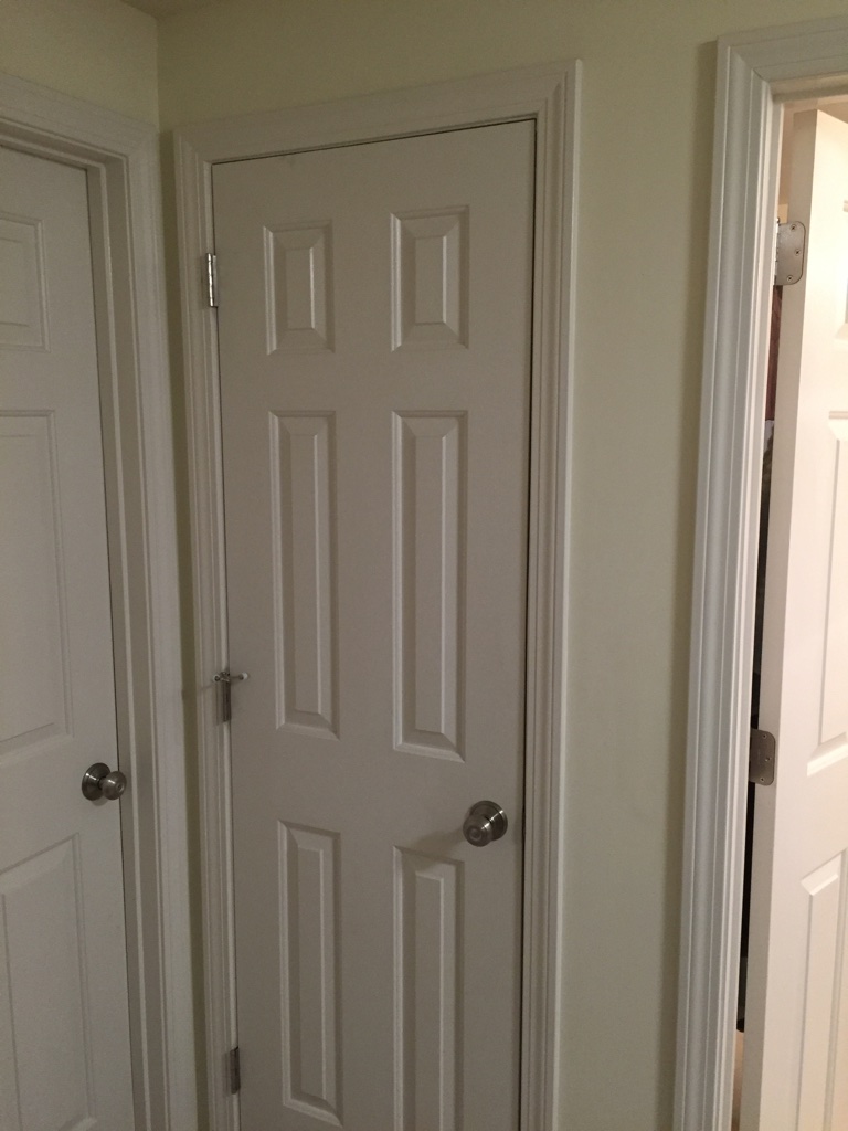
AFTER: Properly adjusted door with new Schlage ‘Georgian’ style knobs. The knobs and hinges are finished in brushed nickel.
What if all the gaps look good, but now the door knob won’t catch on the strike plate?
If the strike plate is now way off, say 1/4″ or more– double check to make sure you haven’t misaligned anything. If you are confident in your work and happy with your gaps you could remove the strike plate, use the doweling repair method above, cut a new mortise and re-install the strike plate. This can take a lot of time and work and gets ugly as you don’t want to chew up a lot of the wood in the door jamb, graft on wood dutchmen or shims to fill gaps left by the old mortise nor do you want a lot of putty to fill the gap left by the old location. If the strike plate is only off by say 1/8″ or so you may want to consider filing the strike plate. You can take the strike plate off, put it in a vise and file the opening a bit so that the latch now properly catches in the strike plate. Just be careful not to remove so much metal that you weaken the mounting screws’ ability to securely hold the strike plate in place.
Pro-Tip: Files only cut on the push stroke. After each push you should lift the file slightly and then pull back so that you don’t prematurely dull your file(s). Also be mindful that you don’t leave any burs and make sure you are cutting straight up and down in line with the existing opening in the strike plate.
By working through the above steps you should be able to fix most of the common problems you’ll encounter with interior doors. I know I am a lot happier to have all my doors properly closing and staying closed now. And the new hardware color also makes my OCD happy as the older brass hardware always bothered me as I have been slowly replacing/upgrading other hardware around the house to match that more modern design aesthetic and get rid of any remaining brass.
Take care,
-Bill
P.S. This post will be the first in an occasional series of Handyman 101 and/or Woodworking 101 posts to help folks new to this sort of work get acclimated to doing common projects.
If you have specific requests for topics you want to see covered, please let me know in the comments or via the form on the contact page.
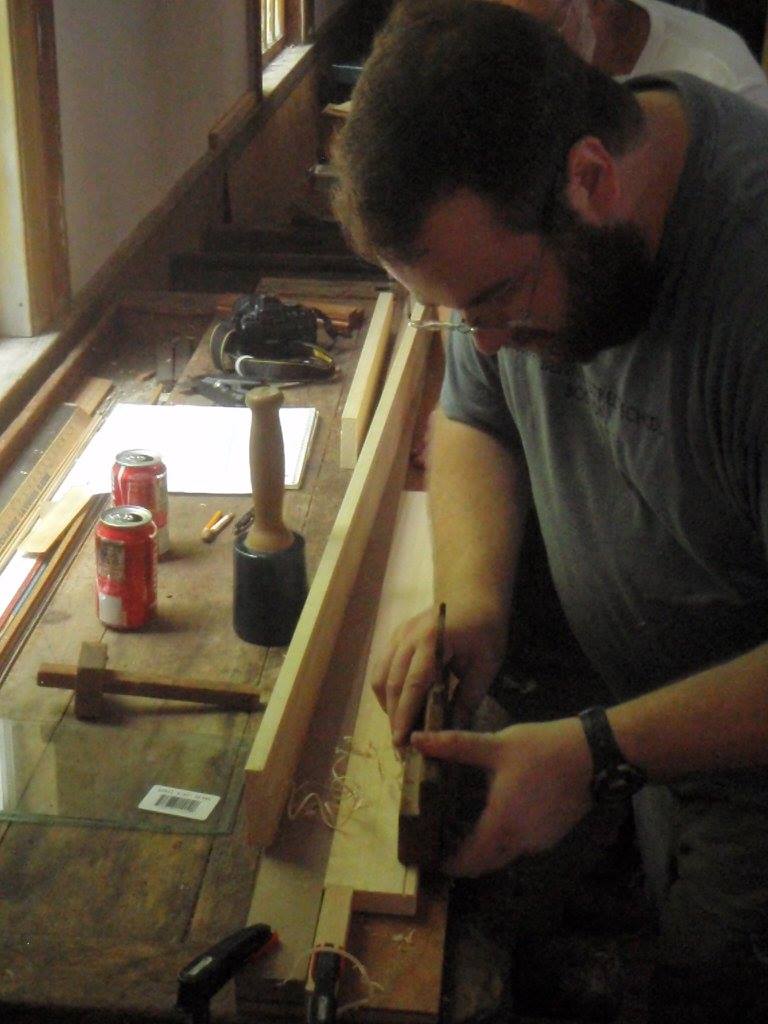
On Saturday I taught a workshop on the use of traditional molding planes to make a picture frame. In this post I’ll cover some of the highlights of the course and share some details for folks who might want to give it a try at home.
Demonstrating the use of a molding plane on a sticking board. (Photo by Carol Coutinho)
One of the joys of an event at Eastfield Village is to work by natural light in a beautiful and immersive setting — in this case Don Carpentier’s village of carefully moved and restored historic buildings — taverns, trade shops, homes and outbuildings.
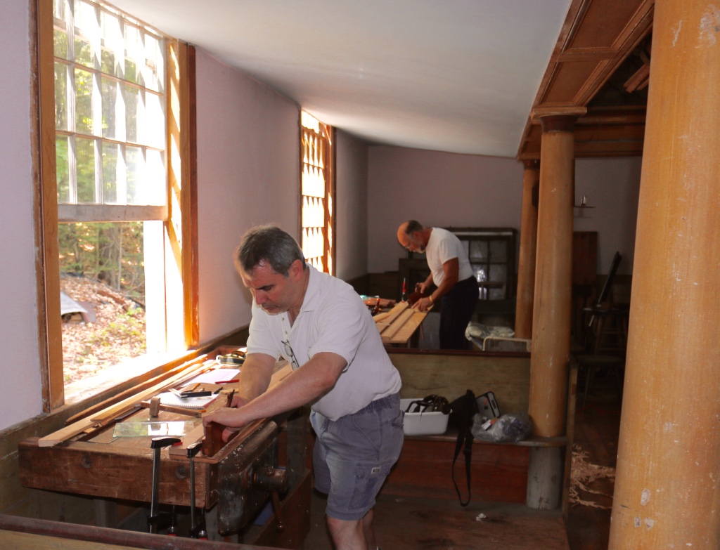
Brian and Tom working with the molding planes.
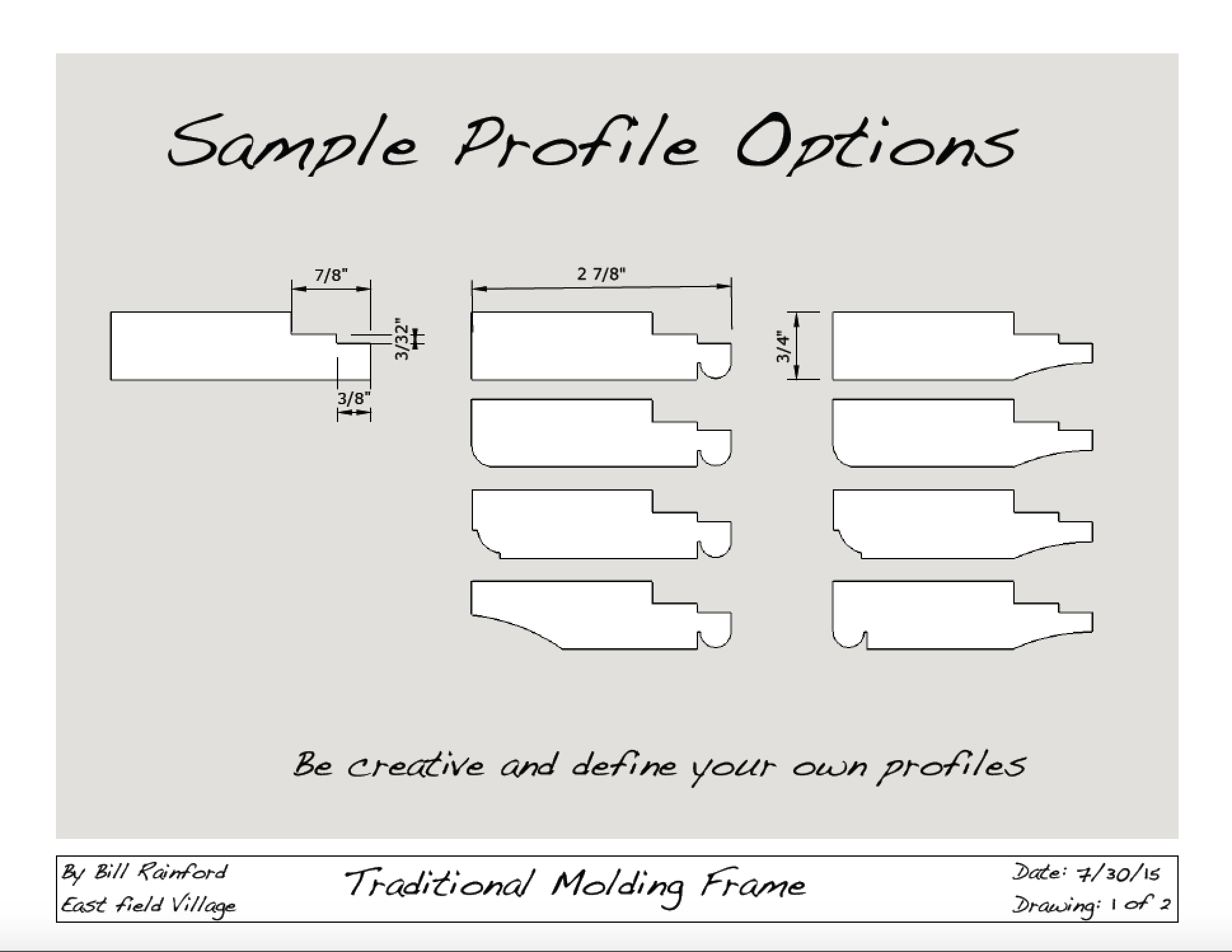
After an orientation to the tools and classroom setup I demonstrated how to evaluate a molding plane and how to tune up an iron. We also talked about the wide variety of profiles that can be created from even a very modest set of molding planes. The profiles below can be created using a beading plane, a pair of hollows and rounds (say #8) and a rabbet plane.
A sampling of how a few simple profiles can generate a large variety of frames.
And with hollows and rounds the profiles are only limited by your imagination.
Students tuned up their planes, squared up their stock, and tested their plane setup on some scrap and set about making the stepped rabbet needed to hold the glass in place and the plywood back. The plywood back is carefully screwed in place and helps created a very solid/rigid frame compared to the floating backs held in by stamped metal retainers we see on many modern store bought frames. The long piece of plywood with an MDF fence and screws at the end to secure the stock is called a ‘sticking board’ and can be as long or as short as your project stock requires.
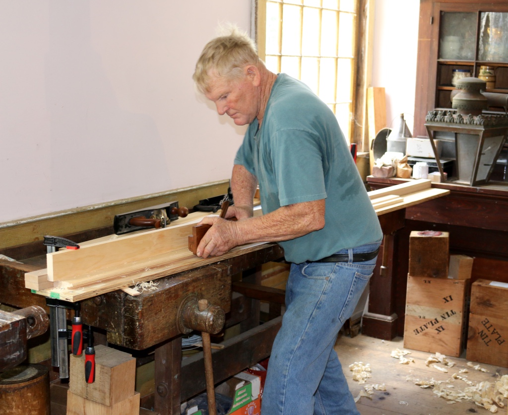
Don making a profile on the edge of his frame stock.
Next up students started molding their chosen profile(s). We talked about how to work backwards withe the molding planes building on the work of an earlier swipe, how to adjust irons as needed and how to get a nice finish on the profile.
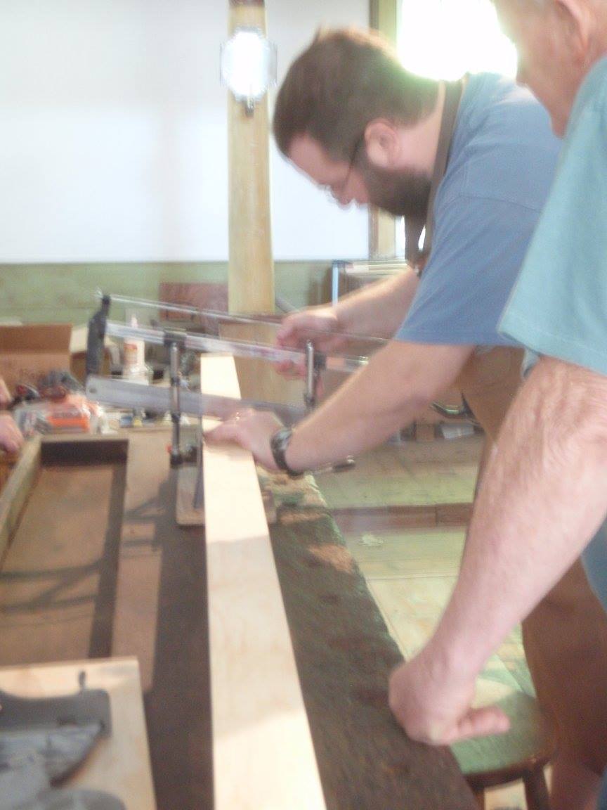
Making the miters with a miter box. (Photo by Carol Coutinho)
With a fully molded piece of stock now it was time to layout your cuts and cut the miters. In this case students left the line knowing that we could creep up on it by using my Lion Mitre-Master (large metal frame-makers guillotine) or a shooting board with 45 degree insert to clean up the corners and ensure we have a nice tight miter at each corner.
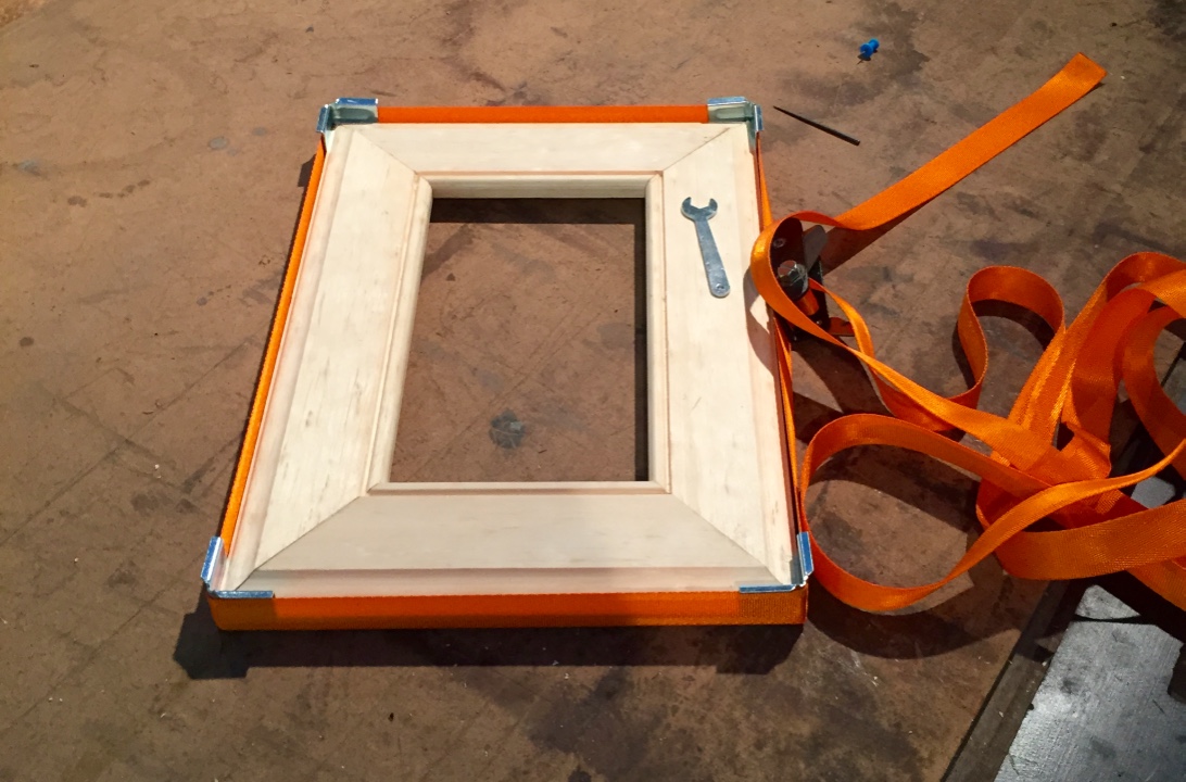
Frame baking in the band clamps
With the woodworking complete, next up was a test fit in the band clamps and then final gluing of the frame. While the frames baked in the clamps it was time to cut the glass to size and test fit it. We did this with a self-oiling glass cutter and a layout I made on the bench. Once the glass was fit it was time to layout and countersink the plywood back which was made if 1/4″ thick Baltic birch plywood and secured with #6 1/2″ waxed screws. We used bit braces and egg-beater drills to make quick work of this step.
Hanging hardware came in the form of a self leveling hanger (Think saw-tooth that hangs on single nail) which is affixed with two tiny brads. An appropriate finish would be stain and shellac or a nice bright milk-paint.
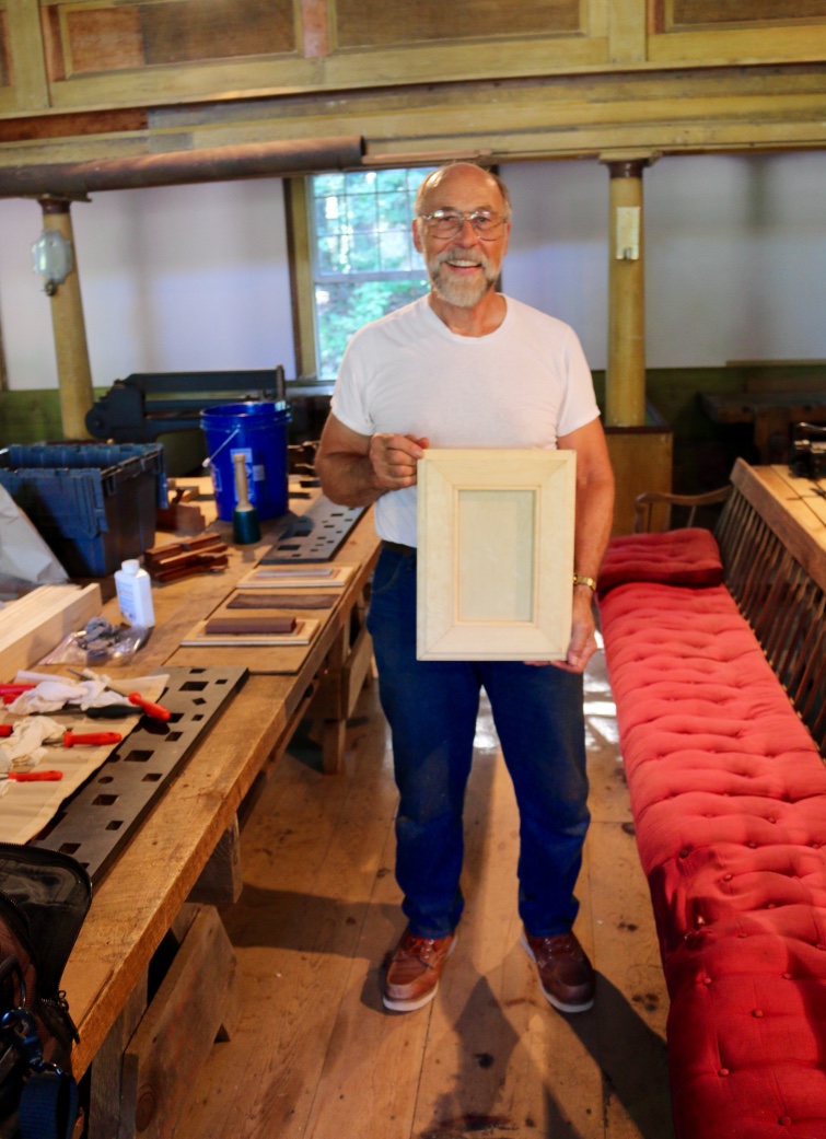
Tom with his finished picture frame.
I’m happy to report that everyone in the class was able to complete their frame, and I had a great time working with Tom, Don, Carol and Brian. (Carol I’m sorry that I didn’t have any photos of you working to add to this post, but I did make use of some of those photos of me you share with me — thanks again) .
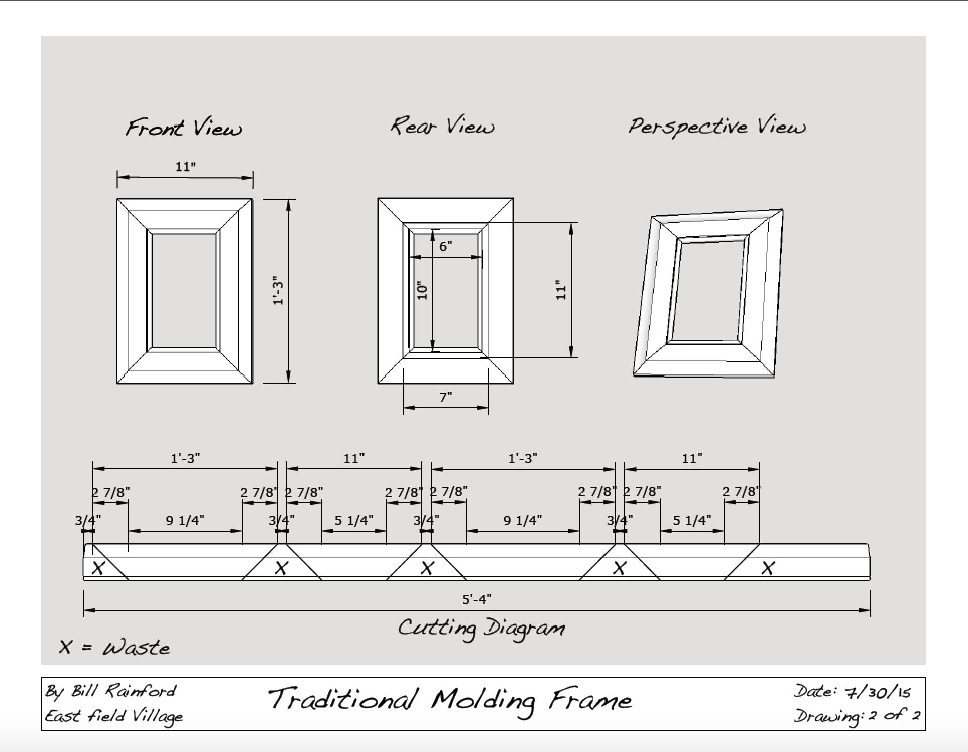
If you’d like to make a frame of your own the plans I put together for this workshop can be seen and downloaded from the link below. The seemingly odd size of this frame was dictated by two factors — the smallest size glass I can get at my local home center is 10×12″ so if you cut it in half you wind up with two 6×10″ pieces which allows each student to have a spare in case their glass cutting didn’t go well and they need a spare or they find time to make a second frame. The size is also dictated by the sticking board and stock. I wanted something that would fit on the 8′ sticking boards I had and allow some extra space in layout and for cutting and to have a bit for testing/trial. The plans below could be scaled up or down to fit whatever size frame you desire.
If you make a frame of your own and take some photos of it, please share it in the comments below. It’s a great project that can add some unique personality to your pictures and add valuable skills to your woodworking repertoire.
Take care,
-Bill
A Joiner's Guide To Traditional Woodworking and Preservation